



Tablet Die Bore Wear Measurement and Inspection Limits
Tablet die bore wear measurement requires more than checking the internal surface for a visible ring. A wear ring can identify a suspect area, but it cannot show how much the bore has enlarged, whether the change is uniform, or whether the die remains within an approved operating limit.
A reliable inspection combines visual examination with controlled dimensional measurements at defined depths and orientations. The results should be compared with the correct tooling drawing, setting reference, or new-tool baseline. Acceptable wear must then be judged against product-specific warning and rejection limits—not a universal value taken from another tooling set.
For broader context on how dies interact with upper and lower punches, see タブレットプレスの金型タイプ. This guide focuses specifically on measuring internal die-bore condition and deciding what to do with the result.
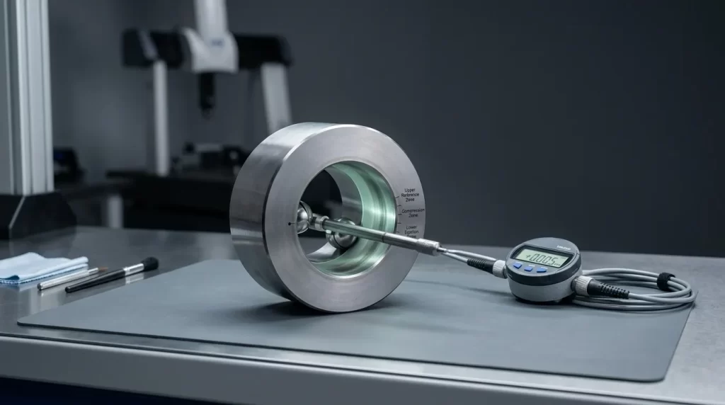
What Tablet Die-Bore Wear Looks Like and Why It Matters
A tablet die bore can experience both dimensional wear and surface deterioration. Dimensional wear changes the bore profile or size. Surface deterioration includes scoring, pitting, corrosion, or roughness that may increase friction even when the diameter has not changed significantly.
A wear ring often develops around the working or compression zone. It may appear as a polished band, a change in reflection, or a visible transition on the internal surface. Its presence should trigger dimensional inspection, but it does not establish a pass or fail result.
Bore enlargement changes the functional clearance between the die and the punch tip. When that clearance becomes excessive or uneven, it can contribute to:
- powder leakage between the punch tip and die wall;
- thin fins or flashing around the tablet edge;
- accelerated punch-tip wear;
- poor tablet-edge definition;
- increased friction or inconsistent ejection;
- unstable performance across tools in the same set.
These symptoms are not proof of die wear. Formulation behavior, lubrication, compression settings, tool alignment, contamination, and punch condition can produce similar problems. They should be treated as inspection triggers.
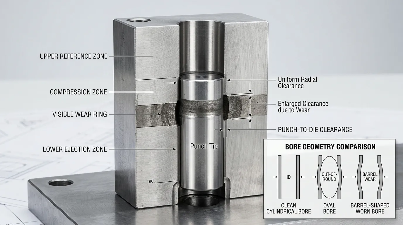
Wear, Residue, Scoring, Taper, or Geometric Distortion?
Several bore conditions can resemble wear or produce misleading measurements.
| 状態 | Typical indication | How to confirm it |
|---|---|---|
| Product residue or filming | Patchy deposit, sticky surface, unstable readings | Clean the bore using the approved procedure, then measure again |
| Wear ring | Localized polished or enlarged band | Measure at several depths above, within, and below the suspected area |
| 表面スコアリング | Linear scratches or grooves | Inspect under directed light and assess surface damage separately from diameter |
| Intentional taper | Gradual dimensional change along the bore | Compare measurements with the controlled tooling drawing |
| Ovality | Different readings at different orientations | Measure at consistent angular positions or profile axes |
| Barrel-shaped wear | Larger reading in the middle than at upper and lower positions | Compare readings across several defined depths |
| Gauge or operator error | Inconsistent results at the same position | Recheck zero, contact position, cleanliness, and measurement technique |
The tooling drawing is essential when a die includes intentional taper or a non-uniform profile. A designed dimensional transition must not be classified as service wear.
Tools and Reference Data Needed Before Measurement
A practical tablet die-bore inspection setup normally includes:
- a suitable split-ball bore gauge or another qualified internal comparator;
- a mechanical or digital deviation indicator;
- the correct setting master or setting ring;
- the controlled tooling drawing and current revision;
- new-tool baseline readings, where available;
- directed lighting or a bore-inspection light;
- approved cleaning materials;
- an inspection record linked to the die or tooling-set ID;
- evidence that the instrument is within its calibration or verification period.
A split-ball bore gauge measures deviation relative to a reference rather than producing a complete geometric scan. The probe must match the bore range and profile being inspected. Original instrument documentation, such as the guidance for a split-ball probe and setting master, should control the setup and handling method.
Calibration status alone does not prove that the measurement method is suitable for the decision. The instrument must also have enough resolution, repeatability, and measurement capability for the inspection limit being applied. The NIST guidance on metrological traceability distinguishes traceability from fitness for a specific measurement purpose.
Split-Ball Bore Gauge Versus Plug Gauge
| 検査方法 | Main use | 制限 |
| Split-ball bore gauge | Measures comparative deviation at selected depths and orientations | Requires correct zeroing, alignment, contact selection, and operator technique |
| Fixed plug gauge | Confirms whether a fixed gauge size can enter a bore | Does not quantify localized enlargement or map wear by depth |
| Optical or coordinate inspection | Can evaluate complex profiles when properly configured | May require specialist equipment, fixturing, software, and validated access to internal features |
A plug gauge can support a pass/fail check for a defined size, but it is not a complete substitute for localized wear measurement.
Drawing, Nominal Size, and New-Tool Baseline
Before measuring, confirm:
- the correct die or tooling-set ID;
- the correct drawing revision;
- the nominal bore profile and units;
- whether the die has an intentional taper;
- the reference positions used for dimensional control;
- any measurements recorded when the die was new.
The nominal drawing dimension defines the intended design, while a new-tool baseline records the actual starting condition at controlled locations. Keeping both makes later wear trending more reliable.
How to Measure Tablet Die-Bore Wear
The approved site procedure and the gauge manufacturer’s instructions should take priority over a general guide. The sequence below shows the controls that a repeatable inspection process should contain.
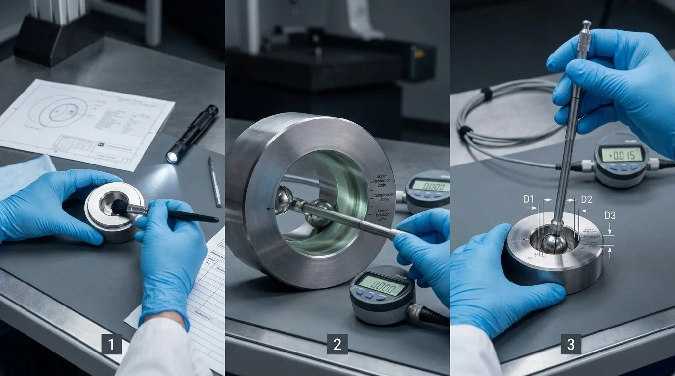
Step 1 — Identify, Clean, and Visually Inspect the Die
Record the die ID before cleaning or measuring. Confirm the drawing revision and previous inspection status.
Clean the bore thoroughly using the approved method. Product residue, polishing compound, lubricant, or corrosion products can alter the contact between the gauge and bore wall.
Inspect the full internal surface under directed light. Record visible conditions such as:
- a polished or enlarged wear ring;
- scoring or scratches;
- pitting or corrosion;
- cracks, chips, or edge damage;
- residue that remains after cleaning;
- a visible taper transition;
- localized discoloration or roughness.
Photographs can help preserve evidence when unusual damage is found. For regulated pharmaceutical operations, written cleaning, maintenance, and inspection procedures should follow applicable requirements such as 21 CFR 211.67.
Step 2 — Set and Verify the Gauge Reference
Select the correct gauge range and contact configuration for the bore.
Clean and inspect the setting master. Place the probe in the master according to the instrument instructions, then align or rock it as required to locate the correct comparative point. Set the indicator to zero or to the documented reference value.
Record the gauge and indicator identification. After the complete measurement series, return to the setting master and verify that the reference has not shifted. A changed zero may indicate drift, contamination, loose setup, or handling error.
Step 3 — Measure a Round Die at Defined Depths and Orientations
Do not rely on a single reading near the bore entrance. Localized wear may exist only in the compression or ejection region.
Define repeatable measurement positions from the tooling drawing and inspection procedure. A typical measurement map may include:
| Measurement region | 目的 |
| Upper reference zone | Establishes the condition above the main working area |
| Compression or wear-ring zone | Detects localized enlargement where the tablet is formed |
| Lower or ejection zone | Checks the region that influences tablet release |
| Additional transition positions | Confirms taper, barrel shape, or local damage |
At each depth:
- place the probe without dragging or forcing it against the bore;
- align it according to the approved technique;
- record the comparative reading;
- repeat the reading to check consistency;
- measure at additional orientations where required;
- record the maximum, minimum, and repeated values.
Different readings by depth can indicate localized or barrel-shaped wear. Different readings at the same depth but different orientations may indicate ovality or directional damage.
The exact depths should come from the die geometry and inspection SOP. One universal set of depth values cannot suit every die design.
Step 4 — Measure Oblong and Shaped Dies by Profile
An oblong or shaped die cannot be represented by one diameter reading.
Use the drawing to identify:
- the major axis;
- the minor axis;
- critical radii or profile transitions;
- orientation references;
- measurement locations at each required depth.
Record every result with both its depth and profile orientation. Suitable contacts or a different inspection system may be needed for complex shapes. If the available gauge cannot contact the required surfaces consistently, do not force a result. Escalate the inspection to the tooling supplier or a qualified metrology process.
| Die profile | Minimum measurement approach |
| Round | Multiple depths and consistent angular orientations |
| Oval or oblong | Major axis, minor axis, and repeated depths |
| Complex shaped profile | Drawing-defined contact points, radii, axes, and specialist method where required |
Step 5 — Repeat, Record, and Confirm the Measurement Series
Repeat any unstable reading. If repeated values differ beyond the approved measurement-system capability, check:
- bore cleanliness;
- probe contact position;
- gauge alignment;
- indicator mounting;
- setting-master cleanliness;
- zero stability;
- contact wear or damage;
- operator technique.
The inspection record should contain more than a pass/fail result. Useful fields include:
- die or tooling-set ID;
- 図面番号と改訂;
- nominal profile;
- measurement depth;
- orientation or axis;
- repeated readings;
- maximum and minimum deviation;
- visual observations;
- instrument ID;
- setting-master ID;
- inspector and date;
- warning, rejection, or monitoring status;
- final disposition.
Recheck the setting master after the measurement series. If the reference has shifted, investigate and repeat affected readings.
How to Establish Tablet Die-Bore Inspection Limits
There is no reliable universal wear limit for every tablet die.
A numerical example from another manufacturer, product, or tooling set may be inappropriate because the acceptable bore condition depends on:
- punch-tip and die geometry;
- original tooling tolerances;
- tablet shape and edge requirements;
- formulation behavior and abrasiveness;
- powder leakage or flashing sensitivity;
- ejection performance;
- press condition and alignment;
- measurement-system capability;
- validated process and product history.
Industry guidance on monitoring punch and die wear also treats acceptable deviation as product-dependent.
A new-tool manufacturing tolerance is not automatically the same as an in-service rejection limit. The first controls how the tool is produced. The second determines whether a used die still supports acceptable production.
Inputs for Warning and Rejection Limits
Use controlled evidence to establish two separate levels where appropriate:
- Warning limit: triggers investigation, shorter reinspection intervals, or increased process monitoring.
- Rejection limit: triggers quarantine, removal from service, or replacement.
The decision should consider:
| 入力 | なぜ重要なのか |
| Tooling drawing | Defines the intended profile, taper, and original dimensional requirements |
| New-tool baseline | Shows the actual starting readings at controlled positions |
| Punch-tip condition | Helps evaluate functional punch-to-die clearance |
| Tablet edge and dimensional quality | Shows whether the tooling still produces acceptable tablets |
| Flashing or powder leakage history | May indicate increasing functional clearance |
| Ejection-force trend | May reveal friction, buildup, roughness, or wear requiring investigation |
| Formulation and run history | Helps explain differences in wear rate |
| Measurement repeatability and uncertainty | Determines confidence in readings near the action limit |
| Supplier recommendations | Adds design-specific guidance when supported by the exact tooling |
| Site validation and change control | Connects the limit with approved product and process performance |
The limit should be written into the inspection SOP with the reference data, measurement positions, required repetitions, responsibilities, and disposition rules.
How to Handle Borderline Results
A reading close to the action limit should not receive an automatic pass or fail when measurement uncertainty could change the decision.
Use a controlled confirmation process:
- clean the bore and setting master again;
- verify the gauge zero;
- repeat the measurement;
- use a second qualified operator if required;
- compare the result with nearby depths and orientations;
- review recent tablet-quality and process data;
- confirm with a more capable measurement method when necessary;
- quarantine the die until the result is resolved;
- document the final decision.
How to Interpret the Results and Choose the Next Action
| Inspection finding | Recommended action |
| Unstable reading or visible contamination | Clean, verify zero, and remeasure |
| Stable result within the approved limit and no unacceptable damage | Return to service and retain the record |
| Result approaching the warning limit | Shorten the reinspection interval and review process trends |
| Result close to the limit relative to measurement uncertainty | Quarantine and confirm with a qualified method |
| Rejection limit exceeded | Remove the die from service |
| Severe scoring, cracking, chipping, or unsafe damage | Quarantine regardless of diameter result |
| Drawing or profile requirement unclear | Request supplier or engineering review |
| Repeated wear across multiple tools | Review punch condition, alignment, material, formulation, and operating conditions |
Do not assume that dimensional enlargement is the only rejection reason. Surface damage can make a die unsuitable even when its measured diameter remains within the dimensional limit.
Process Symptoms That Should Trigger an Unscheduled Inspection
An unscheduled die-bore inspection may be justified when production shows:
- rising or unstable ejection force;
- difficult tablet release;
- new flashing or powder leakage;
- unusual punch-tip scoring;
- binding or increased friction;
- a change in tablet-edge definition;
- recurring chipping, capping, or lamination;
- inconsistent performance among stations using the same tooling set.
Worn, rough, scratched, or contaminated die surfaces can affect ejection friction, but ejection force also depends on formulation, lubrication, tablet geometry, and compression conditions. The relationship is explained in this technical overview of ejection force in tablet compression.
These symptoms should trigger investigation, not an immediate conclusion that the die bore is worn.
Common Tablet Die-Bore Measurement Errors
| Error | Possible effect | Prevention |
| Measuring a contaminated bore | False enlargement or unstable readings | Clean and visually inspect first |
| Using the wrong probe range or contact | Poor contact or misleading values | Match the gauge to the bore and profile |
| Skipping setting-master verification | Incorrect reference | Verify before and after the series |
| Measuring at inconsistent depths | Results cannot be compared over time | Use drawing-defined positions |
| Ignoring orientation | Ovality or directional wear may be missed | Record axes or angular positions |
| Taking only one reading | Operator error may go undetected | Repeat measurements |
| Excessive tilting or rocking | Artificial maximum or minimum values | Follow the qualified gauge technique |
| Using the wrong drawing revision | Designed geometry may be classified as wear | Confirm document control before inspection |
| Ignoring intentional taper | Normal design variation may appear defective | Compare all results with the drawing |
| Relying only on calibration status | Method may lack adequate resolution or repeatability | Confirm measurement capability against the inspection limit |
| Recording only pass or fail | Wear trends are lost | Retain raw values and locations |
Inspection Frequency, Records, and Wear Trending
Measure new tooling before production use where practical. This creates a baseline for later comparisons.
After that, inspection frequency should reflect:
- tooling usage;
- formulation abrasiveness;
- previous wear rate;
- product-quality risk;
- process symptoms;
- proximity to the warning limit;
- maintenance or cleaning events;
- the site’s validated procedure.
A fixed calendar interval may be insufficient. A die approaching its warning limit may require shorter intervals, while stable tooling with a documented history may follow the approved routine schedule.
Trend the actual readings by die ID, depth, orientation, and date. This allows the toolroom to see whether wear is stable, accelerating, or isolated to one region.
Die-bore measurement is only one part of a complete tooling inspection program. Punch dimensions require separate controls; see tablet punch working length inspection for that adjacent procedure.
For applicable pharmaceutical operations, routine calibration, inspection, checking, and records for mechanical or electronic equipment should follow written programs such as those described in 21 CFR 211.68.
When to Involve the Tooling Supplier
Supplier or specialist review is appropriate when:
- the original drawing is unavailable;
- the baseline condition was never recorded;
- intentional taper or profile geometry is unclear;
- a shaped bore cannot be measured reliably with the available equipment;
- borderline results remain unresolved;
- repeated wear suggests a wider tooling or process issue;
- a replacement die must match an existing tool set.
Provide enough information for a meaningful review:
- tooling and die identification;
- drawing and revision, if available;
- tablet and die profile;
- measurement depths and orientations;
- raw inspection readings;
- photographs of wear or damage;
- punch-tip condition;
- production symptoms;
- the required replacement or review objective.
SunshineProリスト custom tablet press tooling, including punches and dies, and states that custom processing can be based on drawings or samples. When measured wear has reached the approved rejection point or the original profile requires review, the practical next step is to submit the available drawing, sample, and inspection findings for a replacement-tooling discussion.


脚本:トンモイ
ニュース
サービスを受けましょう
あらゆる予算に合った高品質な部品と、親切なスタッフが訓練されており、訪問を有益で手間なく提供します。
