



ファインブランキング用のパンチピン: クリアランス, フィニッシュ, そしてエッジ品質
Punch pins for fine blanking cannot be selected by hardness, コーティング, or nominal diameter alone. Edge quality depends on how the punch works with the die, blankholder, V-ring, counterpunch, work material, 潤滑, and press alignment. Very small clearance makes the process especially sensitive to profile error, エッジの摩耗, 表面損傷, and side loading.
This guide focuses on those fineblanking-specific requirements. ダイの種類に関するより広範な情報, tooling materials, and general purchasing considerations, 参照 パンチダイズガイド (推論).
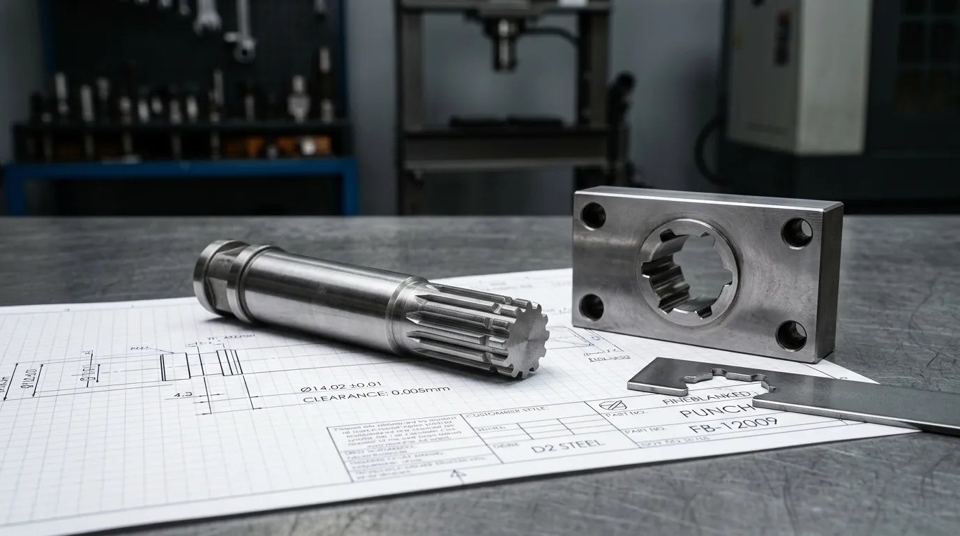
ファインブランキングパンチにシステムレベルの仕様が必要な理由
Fineblanking produces a high proportion of controlled shear by restraining the sheet before and during cutting. The blankholder clamps the material, a V-ring or impingement ring limits lateral flow, and the counterpunch applies pressure from the opposite side. The punch and die then separate the material through a very small clearance.
This system changes the stress state around the cutting line. It can reduce the fracture zone and improve edge perpendicularity compared with conventional blanking, but it also makes tooling errors more visible. A punch that is dimensionally correct on its own may still perform poorly if the guide fit, die position, counterpressure, or material condition creates uneven local clearance.
ある 査読付きファインブランキング研究 describes the interaction among clearance, V-ring geometry, counterpressure, cutting-edge preparation, およびマテリアルフロー. This relationship is why a fineblanking punch should be specified as one part of a matched system.
Distinguish the Blanking Punch, Piercing Punch, and Generic Punch Pin
“Punch pin” is a broad product term. In a fineblanking application, the drawing should identify the actual cutting function.
| 工具に関する用語 | 機能 | 通常制御される次元 |
|---|---|---|
| ブランキングパンチ | 保持部品の外部プロファイルを切断します | 完成したブランクのサイズを制御するダイオープニングで動作します |
| 貫通パンチ | 内部に穴や開口部ができる | 完成した穴のサイズを制御することが多いです |
| パンチピン | いずれの機能も説明できる一般的な用語 | 図面やRFQで明確にする必要があります |
This distinction matters because the punch and die are not dimensioned or edge-prepared in the same way for external blanking and internal piercing.
Using only “punch pin” on an RFQ leaves several questions unanswered:
- Is the finished feature an external blank or an internal hole?
- Which member controls the finished dimension?
- Which cutting edge must remain sharp?
- Where is the intended radius or edge preparation?
- Is the punch guided through a plate?
- How is clearance defined?
These details affect the punch profile, 開業, 検査方法, and regrinding plan.
最先端の準備をブランキングやピアスに合わせましょう
For standard external fineblanking, the punch cutting edge is generally kept sharp while the corresponding die edge is prepared with a controlled radius. ピアスにおいて, the relationship is reversed: the piercing punch receives the relevant edge preparation while the die edge remains sharp.
This blanking-versus-piercing distinction is supported by fineblanking research and should be shown explicitly on the tool drawing. It should not be left to a generic note such as “break all sharp edges.”
Uncontrolled polishing can be just as harmful as an incorrect radius. Polishing the cutting edge may:
- Round an edge that should remain sharp.
- Change the effective punch profile.
- Increase local clearance.
- Produce inconsistent edge preparation around corners.
- Remove a coating from a critical area.
- Hide grinding damage without correcting the underlying geometry.
Edge preparation should therefore be specified by location and function. The punch face, 側面, guide surface, and cutting edge do not necessarily require the same treatment.
Set Clearance by Material, 幾何学, and Edge Requirement
Fineblanking uses much smaller punch–die clearance than conventional blanking. Small clearance supports a larger clean-shear zone, but it also increases cutting force, 摩擦, 熱, and sensitivity to alignment.
Some technical literature cites clearance around 0.5% of sheet thickness as a basic fineblanking guideline. The same research warns that this value must be adapted to the geometry and application. It is a starting point for engineering evaluation, not a universal production specification.
The final clearance decision should account for:
- Material grade and condition.
- Sheet thickness and thickness tolerance.
- 硬度, 引張強度, and ductility.
- Microstructure and rolling direction.
- Part profile and corner geometry.
- Required clean-shear depth.
- Allowed fracture zone and burr height.
- V-ring and counterpunch forces.
- Punch and die rigidity.
- 潤滑.
- Tool material and cutting-edge condition.
- Expected wear during the production run.
Clearance should be validated against the assembled tool and actual work material. A punch supplier cannot establish finished edge quality from the punch drawing alone if the die, ガイドシステム, force settings, and material condition are unknown.
Specify Per-Side, Total, and Relative Clearance Correctly
A drawing should state whether the listed clearance is per side or total.
For a symmetrical profile:
- 片側クリアランス, c: gap between the punch and die on one side.
- 総クリアランス: combined clearance across both sides, normally 2c.
- Relative clearance: per-side or total clearance expressed as a percentage of sheet thickness. The convention must be stated.
例えば, if the per-side clearance is shown as 0.01 mm, the total diametral difference between a round punch and die opening is 0.02 mm. This is only a dimensional illustration, not a recommended fineblanking value.
The controlling dimension also changes with the operation:
- In external blanking, the die opening normally controls the retained blank profile. The punch is smaller by the total clearance.
- ピアスにおいて, the punch normally controls the hole profile. The die opening is larger by the total clearance.
A complete drawing should identify:
- Whether the operation is blanking or piercing.
- The finished feature dimension.
- The punch dimension.
- The die dimension.
- Whether clearance is per side or total.
- The relevant datums and geometric tolerances.
Without these details, two suppliers may interpret the same clearance note differently.
Diagnose Clearance That Is Too Small, Too Large, or Uneven
| クリアランス条件 | おそらくエッジや工具の影響 | 名目価値を変更する前のチェック |
| 大きすぎる | Earlier fracture, wider fracture zone, increased taper, larger burr, reduced clean shear | Punch and die wear, 材料の厚さ, エッジコンディション, actual assembled dimensions |
| 小さすぎる | Higher cutting load, 熱, 摩擦, 腹立たしい, accelerated wear, chipping sensitivity | Force settings, 潤滑, アライメント, punch toughness, corner geometry |
| 横断面の不均一な部分 | One-sided burr, local fracture, サイドローディング, asymmetric wear, エッジの欠け | Punch straightness, 路線, ガイドの状態, ホルダーフィット, profile accuracy |
Uneven clearance is often more damaging than a slightly imperfect nominal value. A drawing may specify the correct average gap while the assembled tool produces a smaller gap on one side and a larger gap on the other.
考えられる原因には以下が含まれます:
- Punch straightness error.
- Worn guide plate or bushing.
- Incorrect shank or holder fit.
- Misaligned die inserts.
- Profile error after regrinding.
- Press or die-set deflection.
- Material feeding at an angle.
- Local coating buildup or damage.
その ダイ部品ガイド provides broader context on guide systems, wear parts, and component alignment. In a fineblanking tool, those components directly influence the clearance that exists under load.
切削刃を傷つけずにパンチ仕上げとジオメトリを指定してください
A single surface-roughness value does not fully define a fineblanking punch. The punch face, 側面, 最先端, guide surface, シャンク, and transition features perform different functions.
The flank slides against the work material and may be exposed to pickup, 得点, and adhesive wear. The guide surface controls positioning and side load. The cutting edge defines the start of material separation. A finish requirement should identify the exact surface and its purpose.
Average roughness, or Ra, is useful, but it can hide isolated deep scratches. Two surfaces with similar Ra values may behave differently if one contains directional grinding marks, torn material, pits, or high peak-to-valley variation.
Where the application is sensitive, the specification may also address:
- Rz, Rt, or another peak-to-valley parameter.
- Measurement direction.
- Measurement location.
- Sampling length and cutoff.
- Maximum scratch depth.
- Visual or optical acceptance criteria.
- Grinding-burn inspection.
- EDM recast-layer removal.
- Coating condition at the cutting edge.
Control the Face, 側面, Guide Surface, and Cutting Edge Separately
| パンチエリア | 主な機能 | 主なリスク |
| 最先端 | せん断を開始・制御する | Rounding, 欠け声, incorrect radius, coating buildup |
| 側面 | 作業資料をスライドで通り過ぎます | 苛立たしい, ピックアップ, 得点, 研磨摩耗 |
| パンチフェイス | 荷重削減による移動 | チップ, 変形, ダメージの挽回 |
| ガイド面 | 制御位置とサイドロード | 過剰なクリアランス, 押収, 不均等な接触 |
| シャンクとトランジション | パンチをホルダーに接続してください | 応力集中, poor fit, 曲げる |
Polishing is useful only when it improves the intended surface without changing geometry. An operator should not polish across a critical edge or remove material until the surface “looks smooth.” The process should preserve profile size, 直線性, エッジコンディション, フィット.
Grinding direction also matters. Deep transverse marks on a sliding flank can increase resistance and create locations for material pickup. Fine longitudinal finishing may be more appropriate on a guided or sliding surface, provided it does not alter the punch dimensions.
Verify Profile Accuracy, 直線性, 同心率, and Runout
Very small nominal clearance requires accurate geometry throughout the punch assembly.
プロファイル精度 controls local clearance around complex shapes. A small profile error near a corner can create excessive pressure even if the main dimensions are correct.
直線性 affects how the punch passes through the guide and enters the die. A long punch with slight bow may contact one side of the guide, producing side load and uneven clearance.
同心率または同軸性 matters for round, ステップド, or multi-diameter punches. It defines how one cylindrical feature relates to another datum axis.
ランアウト is a practical inspection result obtained during rotation. It can reveal eccentricity, surface error, or setup error, but it should not be treated as identical to concentricity.
The inspection plan should also account for:
- シャンク直径と適合度.
- Holder pocket condition.
- Guide-plate clearance.
- Punch protrusion and length.
- Die-insert location.
- Datum selection.
- Regrinding effects.
- Coating thickness on controlled surfaces.
A punch can meet its standalone dimensions and still produce poor results if the assembled tolerance stack shifts the cutting profile.
支配的な故障モードによってパンチ材料とコーティングを選択
The best punch material depends on how the tool is expected to fail. Hardness alone is not a sufficient selection criterion.
Relevant failure modes include:
- Abrasive wear from hard particles or abrasive stock.
- 接着による摩耗と擦り傷.
- エッジチッピング.
- Gross fracture.
- 塑性変形.
- Bending or side loading.
- Thermal damage.
- コーティング剥離.
The work material, 厚さ, feature size, corner geometry, punch slenderness, ガイドの状態, 潤滑, and production volume all affect the choice.
普遍的な勝者を宣言せずに鋼とカーバイドを比較する
| マテリアルオプション | 潜在的な利点 | 主な制限 | 適切な考慮事項 |
| HSSまたは工具鋼 | 靭性, エッジの安定性, easier regrinding, better tolerance of impact or slight misalignment | 非常に研磨性の高い用途では摩耗が早くなることがあります | 複素幾何学, 細いパンチ, applications with chipping or impact risk |
| 粉末冶金工具鋼 | 耐摩耗性と耐久性のバランス | より高いコストと材料特有の熱処理要件 | 完全なカーバイド脆性のない従来の鋼よりも耐摩耗性が求められる用途 |
| タングステンカーバイド | 高い圧縮強度と耐摩耗性 | Greater sensitivity to tensile stress, 影響, edge defects, そしてずれ | Rigid, well-guided applications dominated by abrasive wear |
Carbide is not automatically the best choice for every fineblanking punch. A highly wear-resistant carbide punch can chip quickly if the guide system introduces side loading or if a sharp internal corner concentrates stress. A tougher HSS or tool-steel punch may provide more stable service in that condition.
SunshinePro lists HSS grades and carbide among its general punch options. Readers comparing available products can review its 高速鋼パンチ および カーバイドパンチのオプション. The application still requires confirmation against the actual work material, 幾何学, クリアランス, and expected failure mode.
コーティングと潤滑を補助的な制御として扱う
SunshineProがTiNをリストに掲載, TiCN, and DLC among coating options on relevant punch product pages. These coatings may change friction, adhesive-wear behavior, or abrasive-wear resistance, but they do not correct a poor base design.
A coating cannot fix:
- Excessive or uneven clearance.
- Incorrect edge preparation.
- A bent or misaligned punch.
- Inadequate substrate toughness.
- Poor guide fit.
- Unsupported corner geometry.
- Insufficient lubrication.
- Grinding damage beneath the coating.
Coating thickness also matters when the clearance is extremely small. A coating applied to a controlled profile or guide surface may alter the final dimension if the drawing and grinding allowance do not account for it.
Coating selection should specify the substrate, 熱処理条件, coated surfaces, excluded surfaces, 最終寸法, edge treatment, および検査方法.
ファインブランキングエッジを読んで、パンチやプロセスの問題を診断してください
The finished cut edge is a record of how the punch, その, work material, forces, 潤滑, and wear interacted during the stroke.
A fineblanked edge may contain:
- Die roll or rollover: rounded deformation near the entry side.
- Clean-shear or burnished zone: smoother area produced by controlled shearing.
- 破砕帯: rougher area where material separation changes from shear to fracture.
- バー: projection at the exit side.
- テーパー: deviation from a perpendicular cut surface.
その VDI 2906 パート5規格 provides terminology and characteristic values for evaluating fineblanked cut faces. Formal acceptance criteria should be based on the applicable drawing and standard rather than an undefined requirement such as “smooth edge.”
Measure Die Roll, Clean Shear, Fracture, バー, and Perpendicularity
Inspection should cover more than one cross-section. Edge quality can vary around corners, narrow webs, changes in profile direction, and areas affected by material rolling direction.
A practical inspection record may include:
- 測定位置.
- Material grade and lot.
- シート厚.
- Tool identification.
- Stroke count.
- Punch condition.
- Die-roll width or depth.
- Clean-shear depth.
- Fracture-zone depth.
- Burr height.
- Edge taper or perpendicularity.
- Photographs at controlled magnification.
Trend data is often more useful than a single measurement. A gradual increase in burr or fracture-zone depth may indicate progressive edge wear. A sudden one-sided defect is more likely to suggest chipping, ミスアライメント, guide damage, or material-positioning error.
欠陥から原因→チェック→修正マトリックスを使用
| 観察状態 | 可能な原因 | チェック | 方向補正 |
| 破砕帯がより深くなっていく | Excess clearance, worn edge, changed material condition, inadequate material restraint | Measure punch and die, inspect edge, verify material and force settings | Restore geometry, review clearance, confirm material and force conditions |
| Burr increases gradually | Edge rounding, 研磨摩耗, 着物 | Compare against earlier parts, inspect edge under magnification | 残余許容度を確認した後、影響を受けた金型を再研磨または交換してください |
| バーは片側が大きいです | クリアランスの不均一さ, punch bow, ガイドの着用, die misalignment | まっすぐさを確認してください, guide contact, ホルダーフィット, die position | 標準クリアランスを変更する前に、アライメントや摩耗部品の修正を行ってください |
| 素材は側面にくっつく | 苛立たしい, 潤滑不足, rough surface, incompatible coating or substrate | Inspect pickup, フィニッシュ, lubrication delivery, 温度 | Clean and restore surface, 正しい潤滑, review material/coating system |
| 局所エッジチッピング | Brittle substrate, 過負荷, small clearance, 影響, サイドロード, ダメージの挽回 | 骨折箇所の検査, アライメント, corner geometry, 熱処理条件 | 根本原因を取り除き、適切な靭性と摩耗のバランスを選びます |
| 完成した断面ドリフト | 使用歴, 変形, loose holder fit, guide damage, thermal change | Check punch profile, shank fit, ガイド, その, and measurement setup | 制御コンポーネントを復元し、クリアランスの再検証を行う |
These are investigation paths, 自動診断ではありません. Several conditions can create the same visible defect.
For broader analysis of fracture, 曲げる, and fatigue-related failures, 参照 プレス金型のパンチ破損.
Prepare the Drawing, Inspection Plan, and RFQ Before Ordering
A useful fineblanking punch inquiry needs more than a part number and nominal diameter. The supplier must understand the finished feature, work material, mating tool, quality target, および検査方法.
パンチ設計を制御するアプリケーションデータを含める
Provide the following information where applicable:
- Finished-part drawing and critical dimensions.
- Identification of blanking or piercing.
- Work-material grade and condition.
- Sheet thickness and tolerance.
- Material hardness or tensile range.
- Coating or plated condition of the stock.
- Rolling direction when relevant.
- Required die roll, clean-shear depth, fracture limit, burr limit, and perpendicularity.
- パンチとダイの寸法.
- Per-side or total clearance convention.
- Punch material and hardness requirement.
- Cutting-edge condition and specified radius.
- Flank and guide-surface finish.
- 直線性, 同心円, coaxiality, and runout requirements.
- シャンク, ホルダー, and guide interfaces.
- Coating type and coated surfaces.
- Regrinding allowance.
- Expected production environment.
- Existing defect photographs or samples when troubleshooting.
The RFQ should also identify which dimensions are final after coating and which surfaces must remain uncoated.
Request Evidence for Material, 硬度, 幾何学, and Finish
Depending on the part risk and quality requirements, request appropriate documentation such as:
- Material certificate or traceability record.
- Heat-treatment record.
- Hardness result and test method.
- 寸法検査報告書.
- Profile measurement.
- Straightness and runout results.
- Surface-roughness measurement, including location and direction.
- Cutting-edge visual or optical inspection.
- Coating specification and application record.
Some requirements can be verified on the loose punch. Others can only be validated after assembly with the die, ガイドシステム, blankholder, and counterpunch.
The purchase specification should separate those two responsibilities clearly.
SunshineProの検証済み機能をファインブランキング仕様にマッチさせる
SunshinePro states that it supplies punching dies and pins and can manufacture non-standard mold accessories from customer drawings or samples. Its relevant product pages list HSS, tool-steel, and carbide options, along with processes such as CNC machining, 精密研削, EDM on applicable products, and vacuum heat treatment on applicable punch products.
The company website also states general punch-and-pin capability of Ra 0.4 surface finish and dimensional tolerances within ±0.002 mm. These are general capability statements. They should not be treated as proof that the same values are suitable for every fineblanking application or that they guarantee a specific cut-edge result.
A technical inquiry should ask SunshinePro to confirm:
| 検証済みの一般能力 | 申請の詳細確認が必要です |
| 図面やサンプルからのカスタム製造 | 提出されたブランキングや貫通ジオメトリが実現可能かどうか |
| HSS, tool-steel, and carbide punch options | どの基材が予想される摩耗や欠けのリスクに合致するか |
| 精密研削と適用可能なEDMプロセス | How the final profile, エッジ, and recast condition will be controlled |
| 選択されたコーティングオプション | Coating suitability, thickness allowance, and coated surfaces |
| 一般的なRaと許容範囲 | Actual finish, プロフィール, 直線性, and inspection requirements for the application |
Prepare the finished-part drawing, work-material data, clearance definition, mating die information, edge-quality criteria, and inspection requirements before requesting a quotation. You can then パンチ仕様書を審査のために提出してください and ask for confirmation of material, 幾何学, フィニッシュ, コーティング, and inspection feasibility.



サンシャインより書かれました
サンシャインで, 私たちは精密金型部品の専門製造およびサプライヤーです, プレスおよび射出成形用途向けの幅広い製品を提供しています. 私たちの主な焦点はパンチダイスです, イジェクターピンとスリーブ, ガイドポストとブッシング. 高度なCNC加工技術で, 厳格な品質管理, そして強力な生産能力, 私たちは信頼性を保証しています, 高精度部品, また、迅速かつ効率的なグローバル供給のための在庫の標準部品も併用しています.
ニュース
サービスを受けましょう
あらゆる予算に合った高品質な部品と、親切なスタッフが訓練されていて、訪問を有益で手間なく充実させてくれます.
