



金型リミットピンの破損原因:曲げ、摩耗、衝撃による損傷
Mold limit pin failure usually points to more than a damaged pin. Bending often indicates side loading, misalignment, binding, poor support, or loose mounting. Scoring and diameter loss can reveal contamination, incorrect fit, or damaging sliding contact. Mushrooming, indentation, and cracking commonly indicate repeated hard impact, incorrect contact timing, or unequal loading.
A limit pin works as part of a larger mechanical system. Its bore, mounting seat, mating stop surface, surrounding plates, and other 型の標準部品(推測) can all influence how force reaches the pin. Replacing the visibly damaged component without inspecting that system may cause the new pin to fail in the same position.
The correct troubleshooting sequence is:
- Identify the visible failure mode.
- Determine the mechanical condition that could produce it.
- Inspect the pin and surrounding components.
- Confirm the cause with measurements and operating evidence.
- Correct the cause before installing a replacement.
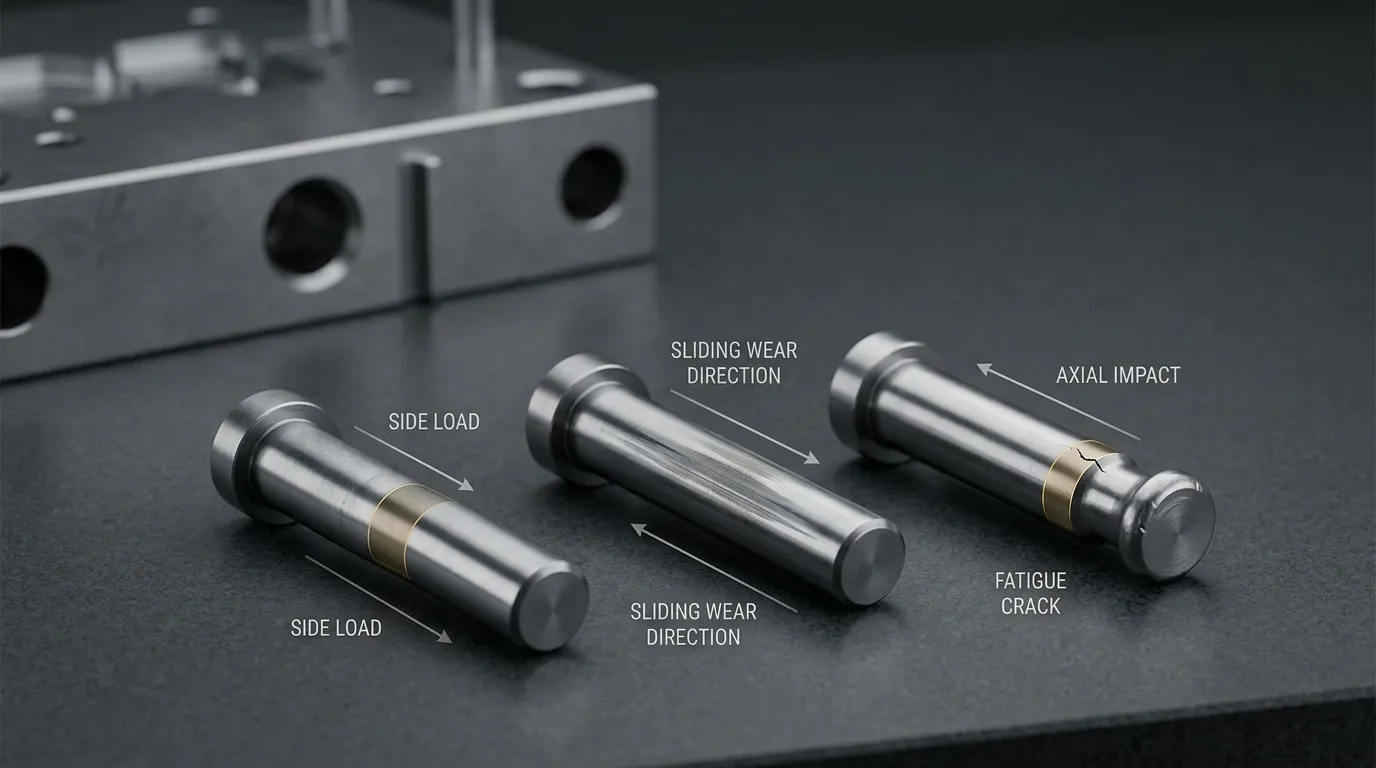
What the Damage Pattern Can Tell You
Physical damage provides useful clues, but one mark rarely proves a root cause by itself. Treat each observation as a starting point for inspection.
| Observed damage | 考えられるメカニズム | Conditions to inspect | Confirming check |
|---|---|---|---|
| Pin bent in one direction | Side loading or eccentric compression | Mold alignment, bore position, binding, contact location, mounting condition | Compare bend direction with wear marks and contact pattern |
| Curved or bowed shank without heavy side wear | Compression instability or buckling | Unsupported length, pin diameter, support condition, obstruction, overload | Check straightness, support points, and installed geometry |
| One-sided polished band | Repeated lateral contact | Misalignment, tilted installation, damaged bore, nonparallel movement | Measure wear around the circumference and inspect the bore |
| Deep longitudinal scratches | 研磨摩耗 | Debris, rough bore, damaged mating surface, inadequate cleaning | Inspect groove direction and look for particles or raised surfaces |
| Smeared or transferred material | 接着による摩耗や擦り傷 | Tight fit, binding, sliding under load, lubrication condition | Check for material pickup on both contacting surfaces |
| Flattened or mushroomed end | Repeated impact and plastic deformation | Stroke, contact timing, stop-face condition, installed height | Compare all corresponding pins and inspect the opposing stop |
| Off-centre indentation | Eccentric impact | Unequal contact, tilted pin, nonparallel plate, damaged stop surface | Examine witness marks and check contact position |
| Crack near a thread, shoulder, or surface defect | Cyclic stress at a stress concentration | Repeated bending, impact, abrupt geometry, machining damage | Preserve the fracture surface and examine the crack origin |
| The same pin position fails repeatedly | Uncorrected local system problem | Bore, seat, stop face, plate alignment, load sharing, thermal movement | Compare that position with neighbouring pins and production history |
Standardized wear terminology is defined in ASTM G40. In practice, the most important distinction is whether material was removed by particles or rough contact, transferred through adhesive sliding, or deformed by direct impact.
Why Mold Limit Pins Bend or Buckle
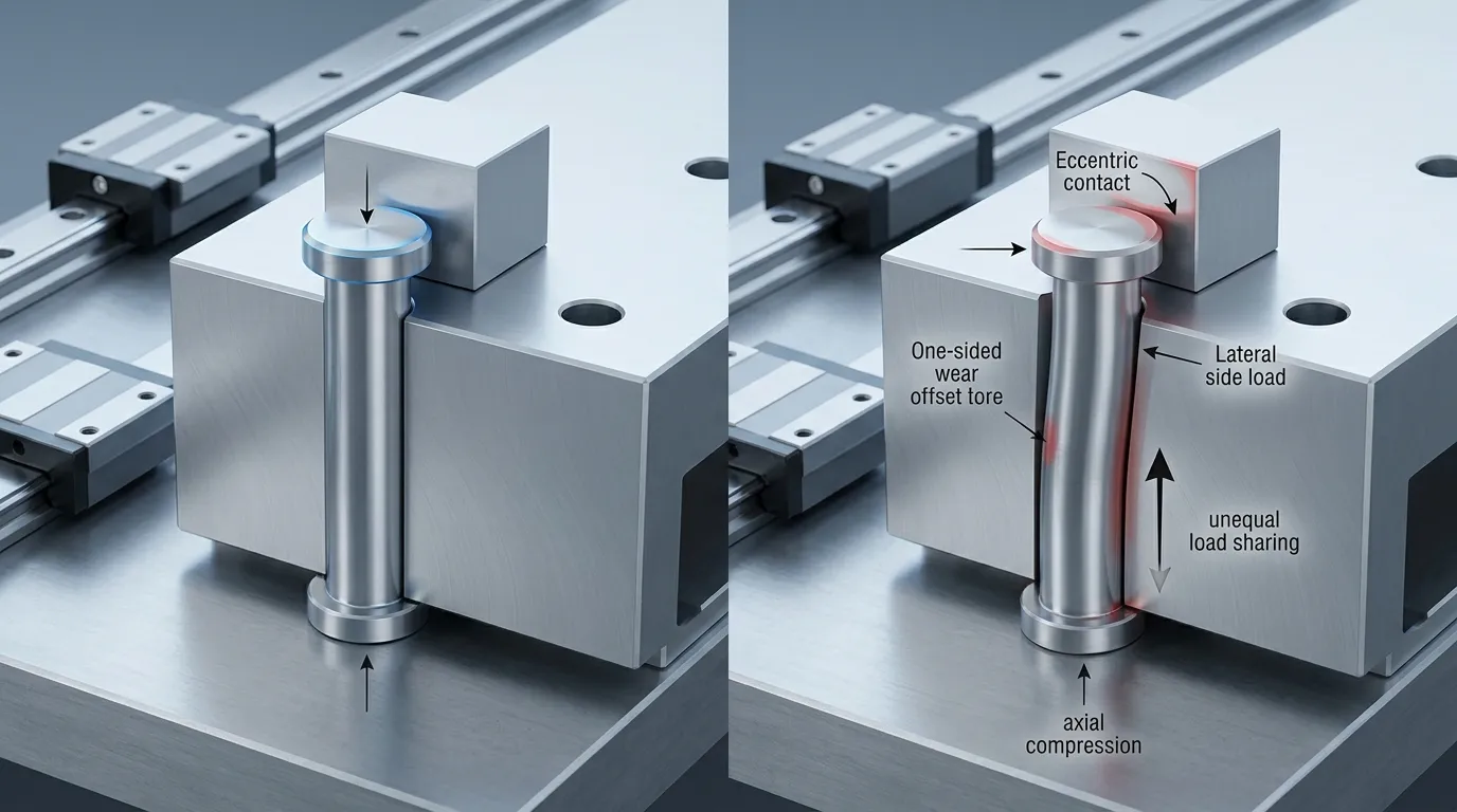
A limit pin normally performs best when force acts close to its centreline. Once contact becomes eccentric, part of the load acts sideways. That lateral component creates bending stress, even when the total machine load has not changed.
Common bending causes include:
- A pin bore that is out of position or no longer straight
- Nonparallel movement between mold plates
- A pin contacting the stop surface away from its centre
- Binding during part of the mold stroke
- A loose thread, retainer, or mounting seat
- Insufficient support along the exposed pin length
- An obstruction that forces the plate or pin sideways
- One pin contacting earlier than the other limit pins
A harder replacement pin does not correct any of these conditions. It may resist some surface wear, but the lateral load will remain.
Misalignment, Binding, and Eccentric Contact
Misalignment changes an intended axial stop into a bending load. The first evidence is often a one-sided wear band, an off-centre mark on the contact face, or a bend that points away from the loaded side.
Inspect the complete movement path:
- Does the pin enter or pass through its bore without side contact?
- Is the bore worn more heavily on one side?
- Do the plates remain parallel through the full stroke?
- Does the pin begin binding only after the mold heats up?
- Do all corresponding limit pins touch at the same time?
- Is the mating stop surface flat and correctly positioned?
Broader problems involving guided movement, fit, and alignment may also involve 型ピンとブッシング. Those components should be inspected when the limit pin’s bending direction matches wider guide-system wear.
Unsupported Length, Overload, and Loose Mounting
A long exposed section is more vulnerable to lateral deflection and compression instability. Under sufficient axial load, a slender or poorly supported pin may bow rather than remain straight. This is different from a pin that bends because its contact point is visibly off-centre, although both conditions can occur together.
Mounting problems can reduce effective support. A pin that is not fully seated may project farther than intended. A loose thread or damaged retainer may allow movement at the base. A distorted mounting seat can tilt the entire pin before it reaches the stop surface.
Check the installed condition against the approved drawing rather than assuming the failed pin had the correct projection, engagement, or support.
Why Limit Pins Wear, Score, or Gall
Not all polished surfaces indicate harmful wear. Light, even contact may simply show where the pin is working. Concern increases when material loss is concentrated on one side, deep grooves appear, the diameter changes measurably, or metal transfers between surfaces.
The location and direction of wear matter:
| 摩耗パターン | Probable cause | 確認すべき点 |
| Even polishing around the circumference | Normal or distributed contact | Diameter loss and drawing limits |
| One-sided polishing | Misalignment or lateral load | Bore position, plate movement, pin straightness |
| Long straight grooves | Abrasive particles or rough bore | Contamination, burrs, damaged counterpart |
| Torn or smeared surface | 接着による摩耗や擦り傷 | Fit, sliding load, heat, lubrication |
| Local wear near the mounting end | Loose support or movement in the seat | Thread, retainer, bore, seating condition |
| Wear that appears only during production | Thermal change in clearance or alignment | Hot-versus-cold dimensions and movement |
Measure the diameter at several positions along the shank and in more than one direction. One measurement near an unworn area can hide localized material loss.
Abrasive Wear from Debris or Rough Contact
Abrasive wear occurs when hard particles or raised surface defects cut or plough the pin. Typical evidence includes directional grooves, fine metallic debris, or a rough track that follows the direction of movement.
考えられる情報源には以下があります:
- Contamination inside the pin bore
- Burrs or raised edges after maintenance
- Damage on the receiving surface
- Corrosion products or hardened deposits
- Wear debris trapped between moving surfaces
Replacing the pin without removing the abrasive source will usually reproduce the same scoring. Clean the movement path, inspect the bore under suitable lighting, and check for raised material rather than looking only for visible dirt.
Adhesive Wear, Galling, and Binding
Adhesive wear develops when loaded surfaces slide against each other and local contact causes material to transfer or tear. Severe adhesive wear is often described as galling. The surface may appear smeared, rough, picked up, or partially seized rather than cleanly scratched.
Contributing conditions include:
- Insufficient working clearance
- Misalignment that forces continuous side contact
- Thermal expansion that closes the available clearance
- Poor surface condition
- Sliding load without suitable lubrication where lubrication is required
Tribology covers the interaction of surfaces in relative motion, including friction, adhesion, lubrication, and wear, as explained by the 国立標準技術研究所.
Lubrication can reduce friction in an appropriate sliding interface, but it cannot correct an off-centre stop, damaged bore, loose mounting, or excessive impact. Applying more lubricant without identifying the contact condition may hide the symptom temporarily while the mechanical cause remains.
Why Impact Damage and Fatigue Cracks Develop
A limit pin that repeatedly strikes its mating surface can deform even when it does not break immediately. The contact face may flatten, mushroom at the edge, develop a local indentation, or begin cracking near a shoulder or thread.
Repeated hard contact may result from:
- Incorrect stroke or overtravel
- Contact occurring earlier than intended
- Different installed heights among several pins
- Nonparallel plates
- A damaged or indented stop surface
- Debris on the contact face
- Excessive speed at the moment of contact
- One pin carrying more load than the others
The impact mark should be near the intended contact area. A mark near one edge suggests eccentric loading and should prompt checks of pin position, plate movement, and the mating stop.
Repeated Hard Contact and Unequal Load Sharing
Multiple limit pins do not automatically share load equally. A small difference in installed height, seat condition, plate alignment, or stop-surface position may cause one pin to contact first. That pin then absorbs the initial impact and may carry most of the load.
Compare all corresponding pins rather than inspecting only the failed one. Look for:
- Different witness-mark sizes
- Different levels of polishing or indentation
- One pin with a mushroomed end while others remain lightly marked
- Debris under one mounting seat
- A recessed or damaged mating stop
- Differences in pin projection
Repeated failure at the same position strongly suggests a local contact or support problem, not random pin quality variation.
Fatigue Cracking After Repeated Bending or Impact
Fatigue develops when cyclic stress initiates a small crack and causes it to grow over repeated load cycles. A pin may eventually fracture even though no single cycle appears severe enough to cause immediate breakage.
Cracks often begin where local stress is concentrated, such as:
- A thread root
- A sharp shoulder
- An abrupt diameter transition
- A deep score
- A damaged contact edge
- A machining or surface defect
ASTM E466 identifies material, geometry, surface condition, hardness, finish, stress, and other variables that can affect fatigue-test results for metallic materials. The standard does not provide a universal service-life value for a mold limit pin.
Do not polish, grind, or discard a fractured pin before the crack origin has been reviewed. Surface alteration can remove evidence needed to distinguish progressive fatigue from final overload.
How to Diagnose the Root Cause Before Replacing the Pin
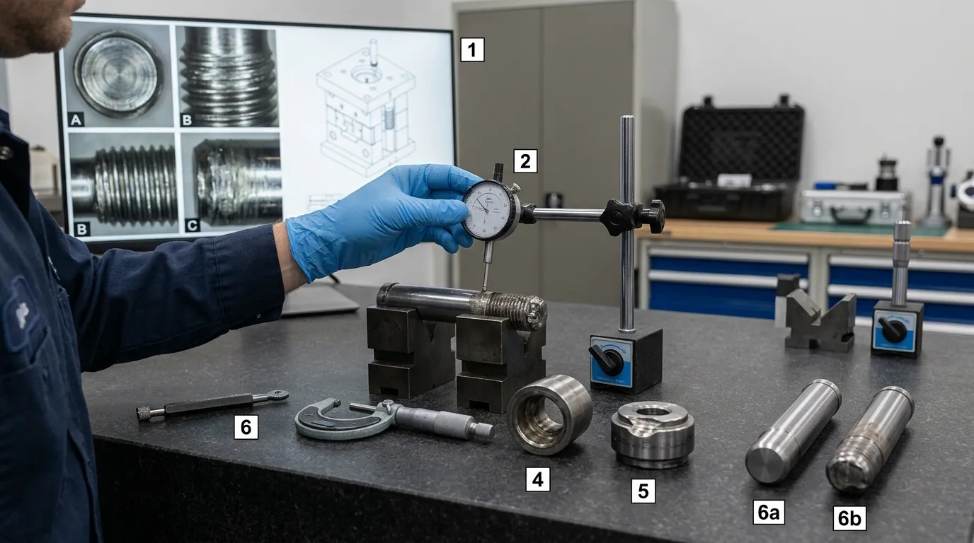
Before entering the mold area or beginning service work, isolate hazardous energy according to the rules that apply at the operating location. In the United States, OSHA guidance for injection-molding machinery requires appropriate lockout and tagout during qualifying servicing work. Interlocks should not be treated as a substitute for proper energy isolation.
Use the following sequence after the equipment has been made safe:
- Record the pin’s installed position and orientation. Mark which side faced the observed wear, bend, or impact.
- Photograph the damage before cleaning. Capture the shank, contact face, mounting area, bore, stop surface, and neighbouring pins.
- Compare all corresponding pins. Differences in wear or impact marks can expose unequal contact timing.
- Check straightness or runout. Do not rely only on visual judgment.
- Measure diameter at several locations. Check more than one direction at each position to identify ovality or one-sided loss.
- Inspect the contact face and transitions. Look for peening, indentation, edge chipping, cracks, and off-centre witness marks.
- Inspect the thread, retainer, seat, and mounting bore. Confirm that the pin was fully seated and securely located.
- Inspect the receiving bore and mating stop. Look for scoring, raised material, indentation, contamination, and unequal contact.
- Compare the findings with the approved drawing or unused part. Acceptance depends on the component’s actual specification, not a universal wear limit.
- Review the operating history. Note when the failure appeared, whether the mold had recently been serviced, and whether the problem changes after warm-up.
Preserve the Evidence Before Cleaning or Reworking
Keep the failed pin in its original condition until the basic investigation is complete. Record:
- Mold and pin position
- Installation orientation
- Production date or cycle period
- Recent maintenance or component changes
- Damage photographs
- Measurements
- Any debris or transferred material
- Hot-versus-cold operating observations
A fracture surface, wear track, or contact mark may contain more useful information than the final dimensional measurement.
Measure the Pin and Inspect the Complete Contact System
The pin should never be evaluated in isolation. A correct replacement installed into a damaged bore or against an indented stop face can fail quickly.
Failure-specific measurements may include:
- Straightness or runout
- Diameter along the working length
- Local diameter loss
- Pin projection or installed height
- Thread or retainer condition
- Seat condition
- Bore diameter and visible wear
- Contact position on the mating stop
- Relative height of paired pins
For broader guidance on tolerance, steel, finish, and supplier inspection, refer to 精密金型部品. The actual acceptance criteria should still come from the approved component drawing or specification.
Match the Confirmed Cause to the Corrective Action
Corrective action should follow the evidence. Avoid changing material, hardness, or diameter before confirming that the failure did not originate elsewhere.
| Confirmed finding | Likely root cause | Corrective action | Replacement implication |
| Directional bend with one-sided wear | Misalignment or side load | Correct bore, plate movement, alignment, or binding | Replace only after restoring the load path |
| Bowed pin with limited side wear | Inadequate support or compression instability | Review exposed length, support, seating, and applied load | Geometry or support may need revision |
| Long abrasive grooves | Debris or rough counterpart | Remove contamination and repair the damaging surface | Do not install a new pin into the same damaged bore |
| Smeared surface or metal pickup | Galling or binding | Correct fit, alignment, surface condition, heat-related clearance, and lubrication requirements | Verify dimensions and surface condition before replacement |
| Mushroomed or flattened end | Repeated hard impact | Check stroke, contact speed, stop face, installed height, and load sharing | Replace only after impact conditions are corrected |
| Off-centre indentation | Eccentric contact | Correct pin position, plate parallelism, or stop-surface geometry | Confirm centred contact with the replacement |
| Crack near thread or shoulder | Cyclic stress concentration | Review geometry, mounting, repeated bending, and impact history | Engineering review may be needed before respecification |
| Loose mounting or damaged seat | Retention failure | Repair the thread, retainer, seat, or bore | A new pin alone is insufficient |
| Suspected hardness or material problem | Incorrect supplied condition or specification mismatch | Verify material and hardness through documentation or testing | Do not assume material failure from appearance alone |
When Replacement Is Enough—and When the Mold Needs Redesign
A like-for-like replacement may be reasonable when the damage followed an isolated event, the surrounding components remain within specification, and the pin’s dimensions, seat, bore, alignment, and contact timing are correct.
Further correction or design review is warranted when:
- The same position has failed more than once
- The pin repeatedly bends in the same direction
- One pin contacts before the others
- The mounting seat or receiving bore is damaged
- The stop face is indented or uneven
- The exposed pin section lacks adequate support
- Operating temperature changes clearance or alignment
- The replacement must differ from the approved drawing
- Material or hardness changes are being considered
Hardness and toughness must be considered together. Greater hardness may improve resistance to some wear conditions, but it does not automatically improve tolerance to impact, stress concentration, or bending.
SunshinePro’s reviewed mold limit pin product page lists S45C with a hardness of 15–17 HRC for that product, along with precision grinding, vacuum heat treatment, standard options, and non-standard customization. Those details describe the listed product; they are not universal specifications for every limit-pin application.
Where formal Rockwell hardness verification is required, the test method should follow an applicable standard such as ISO 6508-1:2023. Test results must also be interpreted against the approved drawing or material specification.
What to Provide for a Replacement or Failure Review
A supplier can review a failed component more effectively when the inquiry includes evidence rather than only a requested diameter and length.
準備:
- The approved drawing or complete dimensional requirements
- The failed pin or a clearly identified sample
- Photographs of the damage and installed orientation
- The pin’s location in the mold
- Straightness, diameter, and wear measurements
- Details of the bore, seat, retainer, and mating stop condition
- Required material and hardness
- Heat-treatment requirements where specified
- Cycle and failure history
- Operating temperature or warm-up-related changes
- Details of recent maintenance or mold modification
- Whether a standard replacement or revised custom part is being considered
SunshinePro states that it supplies standard mold components and drawing-based custom parts, with a workflow covering drawing review, processing, and inspection. After the root cause has been investigated, submit the drawing, damage evidence, measurements, and operating history through the SunshineProの連絡先ページ for a standard or custom limit-pin review.


脚本:トンモイ
ニュース
サービスを受けましょう
あらゆる予算に合った高品質な部品と、親切なスタッフが訓練されており、訪問を有益で手間なく提供します。
