



金型リミットピン設置ガイド: 座席, 保持, およびアクセス
A mold limit pin must do more than fit inside its mounting hole. It must seat against the correct reference surface, project to the drawing-defined height, remain securely retained, and still be accessible when inspection or replacement is needed.
リミットピンはより広いグループに属します。 金型標準部品 (推論), but catalog dimensions alone do not determine whether a pin can be installed correctly. The mold assembly drawing, component drawing, 材料表, mounting-bore condition, and retention design must agree before installation begins.
This guide covers mechanical limit or stop pins that establish a plate-travel, 連絡先, or impact-control position. It does not provide universal fit, torque, insertion-force, seat-depth, or hardness values. Those requirements must come from the approved mold documentation.
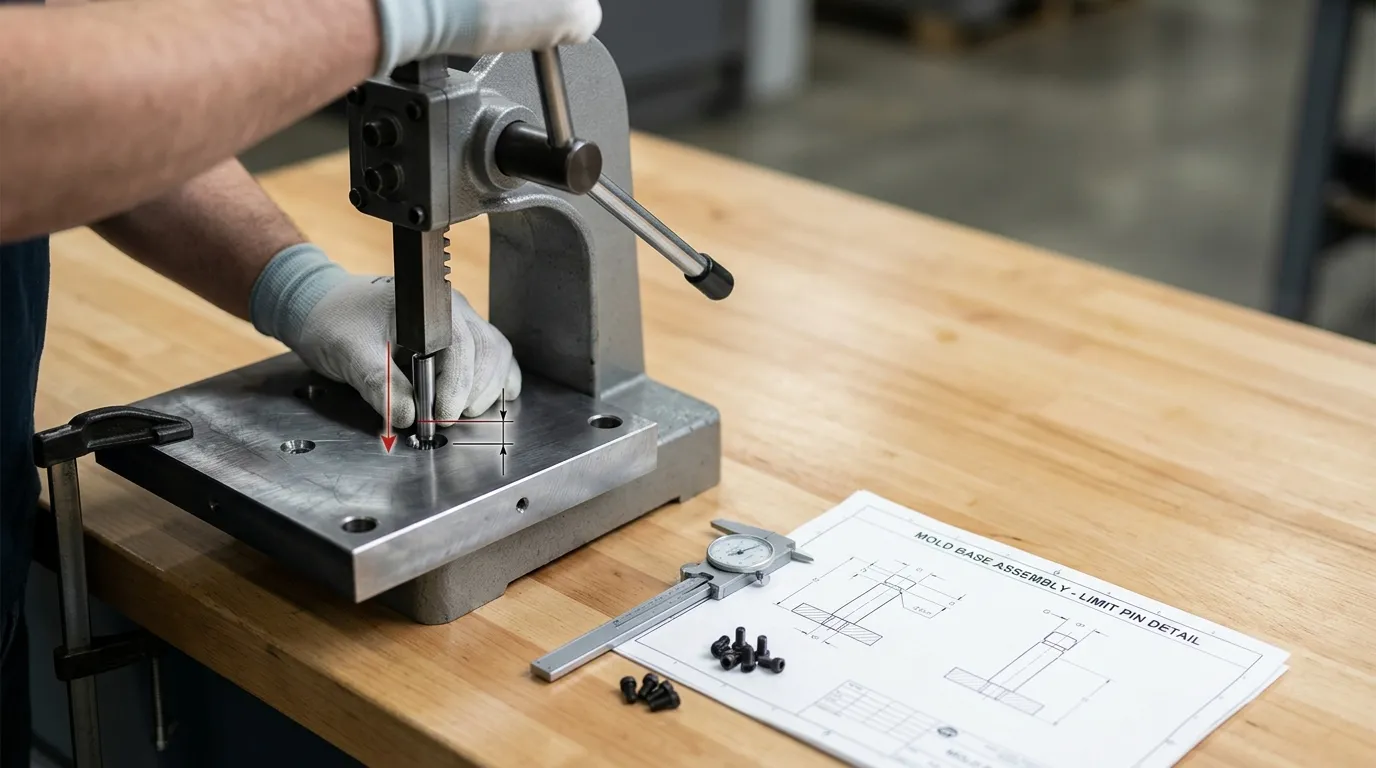
取り付け前にピンの機能を確認してください
The first step is not pressing the pin into the plate. It is confirming what the component is expected to do.
例えば limit pin, stop pin, ガイドピン, ダウエルピン, リターンピン, および イジェクターピン are sometimes used inconsistently. Two pins may look similar while performing different functions inside the mold.
Distinguish Limit Pins from Guide, Dowel, Return, and Ejector Pins
| 構成要素 | 主な機能 | 典型的な関係 | 主な設置上の懸念 |
|---|---|---|---|
| Limit or stop pin | Establishes a travel, 連絡先, or impact-control position | プレートや機構の動きを接触または制限する | 設置された投影, 座席, 保持, and contact height |
| ガイドピンまたはリーダーピン | 動く型と静止型のセクションを整列します | 結合ガイドブッシングを通る | アライメント, fit with the bushing, 潤滑, そして着用 |
| ダボまたは位置ピン | コンポーネント同士の相対的な位置付け | 位置を保たなければならないプレートや部品の間にはまります | 位置精度と相対的な動きに対する抵抗 |
| リターンピン | エジェクター関連機構の返還に役立ちます | 型の閉じ作業中にエジェクターアセンブリと連携 | Travel, 干渉, and return timing |
| Ejector pin | 成形部品をキャビティやコアから押し出します | エジェクターシステムとモールディングエリアを通過します | 長さ, クリアランス, 動き, and contact with the molded part |
Do not assume that a pin is a limit pin because of its shape or location. Check the assembly drawing and BOM designation. The drawing should show which plate carries the pin, which surface contacts it, and what movement the pin is intended to control.
If the component is part of the mold’s alignment system, refer to the separate guide on 型ピンとブッシング rather than applying stop-pin installation logic.
図面とBOMを管理指示として読みましょう
Before removing an old pin or fitting a replacement, 確認:
- 現在の図面改訂
- 部品番号
- 数量と位置
- 管理設置
- ボディの直径と全長
- 肩, ヘッド, フランジ, or threaded features
- 穴またはシャフトフィットのコールアウト
- 取り付け穴の深さ
- 基準座席面
- 必須設置された投影
- 保持方法
- ファスナーアクセス
- 抽出または除去方法
国際標準化機構の ISO 286システム provides recognized terminology for hole and shaft tolerances. It does not tell the installer which fit is correct for a specific limit pin. The approved drawing must make that decision.
Stop the work if the drawing, BOM, and actual component conflict. Additional force will not correct an incorrect part number, obsolete revision, or mismatched geometry.
Prepare the Mold, ピン, and Mounting Feature
Preparation determines whether the pin reaches its intended seat without damaging the bore or plate.
The mold must be safely supported, the component must match the documentation, and the mounting feature must be clean and dimensionally suitable before insertion starts.
カビを安全に隔離し支援する
A mold may contain electrical, 油圧式, 空気圧式, mechanical, gravitational, or spring-loaded energy. Control those hazards under the approved workplace procedure before disassembly or installation.
この一般的な原則は、OSHAの要件と一致しています。 有害エネルギーの制御, although the exact legal and procedural requirements depend on the country, 機械, and workplace.
Before working on the pin:
- Isolate the molding machine and connected systems.
- Release or restrain stored energy.
- Support plates that could shift after a component is removed.
- Position the mold so installation force can be applied in line with the pin axis.
- Confirm that no person is exposed to an unsupported moving plate or ejector assembly.
This is not a substitute for local lockout, メンテナンス, or lifting procedures.
交換用のピンを点検してください
Compare the replacement pin with the latest component drawing rather than relying only on the old pin.
チェック:
- ボディ直径
- 全長
- 肩または頭部の寸法
- 接触面条件
- ねじの大きさと糸の損傷
- 面取りとエッジコンディション
- 表面のスケーリングまたは腐食
- 直線性と目に見える変形
- 部品番号または追跡可能な識別
SunshinePro’s listed Mold Limit Pin product includes product-specific material, 耐性, 硬度, threaded-feature, and customization information. Those figures apply only to the listed product configuration. They must not replace the project drawing or be treated as universal installation values.
Questions involving wider material, 耐性, フィニッシュ, or incoming-QC requirements belong under the broader topic of 精密金型部品.
Inspect the Bore, Counterbore, and Seating Face
A correct pin can still install incorrectly when the receiving feature is damaged or contaminated.
Inspect the mounting area for:
- チップス, grease deposits, hardened residue, or corrosion
- 穴の入り口の周りのバリ
- カウンターボアの周りに盛り上がった金属
- ボア内での刻みや材料移動
- 歪みまたは楕円性
- ひび割れや損傷した座席表面
- 穴の深さが誤り
- 未承認の再ワーク
- 以前の撤去試みによる被害
Remove contamination using an approved cleaning method, but do not enlarge, ポーランド語, グラインド, or reshape the bore simply to make the replacement fit.
Manufacturer assembly documentation commonly requires installers to check counterbores, remove burrs, inspect seating surfaces, and confirm component height before final assembly. The same control principle applies here: clean geometry must be verified before force is applied.
正しい座席と設置された投影を確立する
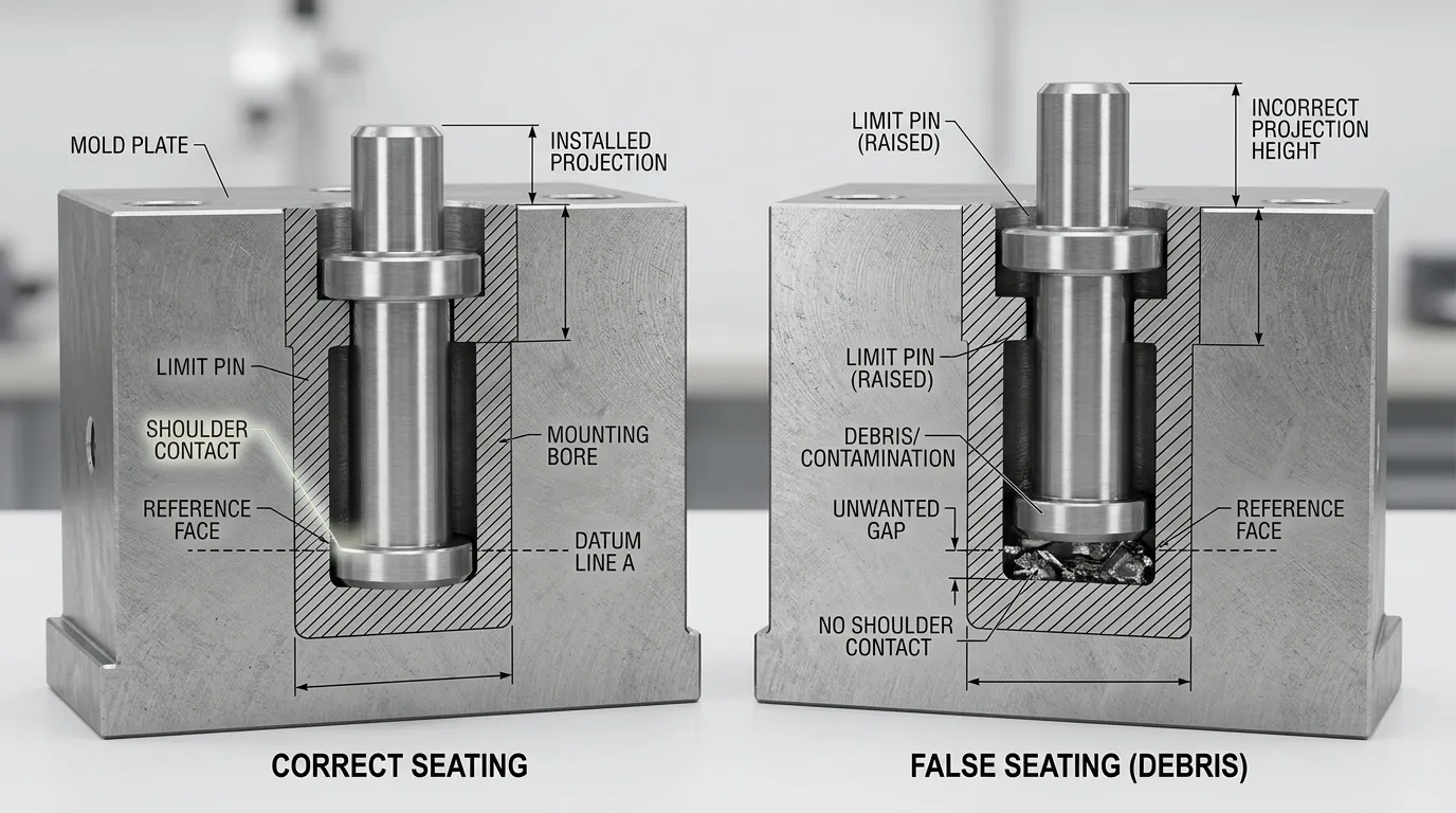
A pin is not acceptable merely because it appears fully inserted.
Its axial position must be established by the intended reference face. 設計によります, that may be a shoulder, ヘッド, フランジ, カウンターボア, リテイナー, or another drawing-defined surface.
基準面と測定基準点を特定する
The drawing should answer two separate questions:
- Where does the pin stop during installation?
- From which mold surface is its exposed height measured?
These surfaces are not always the same.
例えば, a shoulder may seat inside a counterbore while the installed projection is measured from the outer plate face. A threaded or retained design may establish axial position through a head or clamping component rather than through the bottom of the hole.
Use one controlled datum for all measurements. Record that datum with the measured projection so another technician can repeat the inspection later.
A vague instruction such as “press until fully seated” is inadequate unless the seating surface and final height are defined.
ブラインドホールでの偽装座り防止
Blind holes require special attention because the pin can contact the hole bottom before its intended shoulder or reference surface reaches the seat.
False seating may result from:
- 穴の深さ不足
- 底の欠片や破片
- 肩の下のバリ
- 閉じ込められた残留物や損傷した金属
- ピンの長さが誤りです
- 頭や肩の形状が不一致
- 過去の未承認ボア改造
Common warning signs include:
- 過剰な設置投影
- 肩の下に目に見える隙間があった
- 予想外に高い挿入抵抗
- 傾いているように見えるピン
- 名目上同じピン間の異なる設置高さ
Do not apply additional force when these symptoms appear. Remove the pin using the approved method, inspect the hole and component, and compare both with the drawing.
複数のピンが接触している場合の共通高さを確認してください
Several limit pins may form one contact plane. Equal pin lengths do not guarantee equal installed heights because bore depth, 座席の状態, 残骸, プレート歪み, and component geometry can vary.
When multiple pins are intended to contact together:
- Measure every pin from the same datum.
- Compare actual installed projections.
- Check the mating plate for rocking.
- Look for one pin contacting before the others.
- Inspect contact surfaces for uneven marking.
- Confirm that no pin is carrying contact because another pin is seated too low.
The drawing or approved engineering specification must provide the allowable variation. Do not invent an acceptance tolerance from a different mold or catalog.
制御軸支持でピンを取り付けます
Once the component and mounting feature have been verified, install the pin in the direction specified by the drawing.
- Confirm the required fit and installation direction.
- Support the plate close to the mounting area.
- Align the pin axis with the bore axis.
- Place installation tooling against an approved non-functional surface.
- Apply controlled axial force.
- Monitor the pin for tilt, 得点, shaving, or abnormal resistance.
- Stop when the drawing-defined seating condition is reached.
- Measure the installed projection rather than accepting insertion force as proof of completion.
- Inspect the surrounding plate and exposed pin surfaces for damage.
For an interference-fit arrangement, the fit class influences the required assembly force and future removability. That does not justify estimating the force by feel or copying a fit from another component.
Avoid uncontrolled hammer impact. Side loading can cock the pin, damage the hole entrance, deform the plate, or mark the functional contact face.
Heating, 冷却, surface modification, or lubrication should be used only when the approved installation procedure permits it and defines the applicable conditions.
ピンがきれいに取り付けられなかったら停止してください
Stop the operation if you observe:
- 突然または不安定な抵抗
- ピンチルト
- 金属シェービング
- ボアスコアリング
- プレート歪み
- 接触面の損傷
- 過剰投影
- 肩が座りに届かない
- 予想外にゆるいフィット感です
Recheck the part number, fit callout, ボア直径, hole depth, seat geometry, and component condition. A forced installation can conceal the original mismatch while creating a second problem in the plate.
リテンションセキュリティと将来のサービスアクセスをマッチングする
The pin’s fit and its axial retention are related but not always identical.
Some designs depend mainly on interference. Others use screws, スレッド, blocks, プレート, or trapped heads. The correct choice is the one shown in the approved design, not the method that is easiest to apply during maintenance.
セキュリティとサービス性でリテンション手法を比較
| 保持方法 | 主な特徴 | サービスアクセスの考慮 | 主なリスクは確認すべきです |
| 干渉フィット | ラジアルフィットは保持力を提供します | Removal may require rear access, pulling equipment, or plate disassembly | 繰り返し取り除いた後のボア損傷や保持力の喪失 |
| ねじピンまたは保持ネジ | 機械式ファスナーは軸方向の動きを制御します | 組み立て後もファスナーはアクセス可能でなければなりません | Incorrect torque, damaged threads, or inaccessible fastener |
| スクリュークランプ式設計 | ピンは別のネジまたはクランプで固定されます | クランプが露出していれば修理可能です | クランプの動きやアクセス不足 |
| リテイナープレートまたはブロック | プレートやブロックがピンを閉じ込めます | 制御された取り外しが可能かもしれませんが、ファスナーや加工を加えることが伴います | リテーナーの取り付け順序が間違っている |
| 頭や肩が閉じ込められている | 隣接するプレートが部品を捕獲します | 除去にはプレート分離が必要なことが多いです | 今後のメンテナンスは困難になるかもしれません |
| 保持化合物 | 接着剤は円筒形の継手を支えます | 除去および硬化の条件を計画しなければなりません | Incorrect gap, 汚染, 温度, or unapproved use |
Retaining compounds are not a general cure for a loose or damaged bore. Products such as ロックタイト638 have defined gap, 準備, cure, 温度, および材料要件. Use one only when the component design and engineering instructions approve it.
Confirm Front, Rear, and Extraction Access
Before final assembly, confirm how the pin will be inspected and removed later.
確認します。:
- 保持ネジは前方から手が届く
- 後方アクセス用のファスナーが別のプレートによって塞がれます
- プラースレッドは露出したままです
- スルーホールは制御された支持や取り外しを可能にします
- ブラインドホールピンには定義された抽出方法があります
- リテーナープレートは、無関係なシステムを分解せずに取り外しることができます
- The pin’s orientation leaves access to flats, スレッド, or fasteners
- 将来的に除去すると、敏感な板面に力がかかります
A retention method can be mechanically secure and still be a poor maintenance design. Record any plate separation or special tooling required for removal.
設置の測定と検証
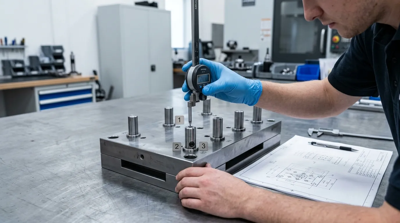
Installation is complete only after dimensional and functional checks confirm that the pin is seated, 保持, アクセス可能, and operating as intended.
Use the approved inspection equipment and the same datum established before installation.
- Measure the installed projection.
- Confirm the pin’s orientation.
- Verify the retention feature.
- Check screw or retainer access.
- Compare the heights of all pins that share contact.
- Check the mating plate for rocking or premature contact.
- Confirm clearance from nearby components.
- Perform an approved test fit or controlled dry cycle.
- Record the result.
メーカーの組み立てマニュアルはこちらから モールドマスター illustrate the broader importance of drawing review, seating checks, 設置高さ測定, clearance verification, and controlled test fitting. The exact acceptance values for a limit pin still come from its own mold documentation.
Record Installed Height, 保持, およびアクセス
The installation record should identify:
- 型または工具番号
- Drawing revision
- ピン部品番号
- 測定基準
- 実際の設置された投影
- 保持方法
- ファスナーの状態
- 前方または後方のアクセス方向
- 抽出方法
- 日付と検査官
- Approved deviations, もし存在する場合
Photographs of the installed pin, 議席, and access arrangement may also help future maintenance teams understand the accepted condition.
管理テストフィットまたはドライサイクルを使いましょう
Follow the approved machine and mold procedure for any movement test.
Observe:
- 接触シーケンス
- プレートトラベル
- 異常な抵抗
- ロッキング
- 干渉
- ファスナーの動き
- ピンの接触の不均一さ
- 意図された位置の前後で停止する機構
Stop the test if the mold does not move or contact as the drawing intends. Do not proceed directly to full-speed production to see whether the problem resolves itself.
一般的なリミットピン取り付け問題のトラブルシューティング
| 症状 | 主な原因 | 必須対応 |
| ピンは高すぎる | バー, 残骸, insufficient blind-hole depth, wrong pin length, wrong shoulder geometry, false bottoming | Remove using the approved method, inspect the seat and hole depth, and compare the part with the drawing |
| ピンが位置が低すぎる | Incorrect seat depth, damaged reference face, wrong component, unapproved material removal | Stop and obtain engineering review; do not shim or modify the pin without approval |
| ピンが傾いています | Cocked insertion, 損傷したボア, サイドローディング, distorted plate, 誤ったフィット | Remove and inspect the bore and pin; check axial support and alignment |
| ピンが緩んでいる | Worn or oversized bore, wrong diameter, missing retention, 誤ったフィット | Do not rely on additional force or adhesive; assess bore repair, redesign, または置換 |
| まず1ピンが接触します | Unequal projection, debris under another pin, mating-surface variation, incorrect component length | 1つの基準点からすべてのピンを測定し、接点面を点検します |
| リテイナーには連絡が取れません | 誤った向き, blocked fastener, poor assembly sequence, insufficient access planning | Correct before final assembly; document any required plate removal |
| ピンが何度も緩む | Incorrect retention, 損傷したボア, changing load path, unsuitable geometry | 設計とエンジニアリングのレビューのためにエスカレートしてください |
Installation should stop when:
- The drawing is unavailable or contradictory.
- The replacement component cannot be positively identified.
- The bore is cracked, enlarged, distorted, or heavily damaged.
- The seat no longer provides a stable reference.
- The required projection cannot be achieved.
- The specified retention cannot be installed or accessed.
- Several pins cannot be brought to the intended contact condition.
- The mold movement does not match the drawing after installation.
Do not use generic drilling, グラインド, 溶接, ピーニング, bonding, or oversizing methods as an automatic repair. Each can change the plate geometry, component fit, serviceability, or contact position.
ピンや取り付け機能の交換や再設計が必要なタイミングを判断してください
A standard replacement may be suitable when the current drawing remains valid and the bore, 議席, フィット感, 保持, and access arrangement are undamaged.
Engineering or supplier review is appropriate when:
- The existing bore is worn or oversized.
- The reference seat is damaged.
- The original drawing does not match the mold.
- A discontinued or altered pin geometry is present.
- The retention method cannot be serviced.
- Required projection cannot be achieved from the existing seat.
- The pin repeatedly loosens.
- Several pins do not share contact correctly.
- A standard component does not match the existing arrangement.
For a replacement review, 準備:
- 現在のピン描画
- 型組み立て図面
- ピンの寸法と形状
- 結合孔の直径と深さ
- 必須設置された投影
- 材料および熱処理の要件
- 保持方法
- アクセスおよび抽出制約
- 適切な場合は写真または物理的なサンプルを添付してください
SunshineProは専用の電源を供給すると述べています 型リミットピン製品 and can discuss custom mold accessories from drawings or samples. The exact material, 耐性, 幾何学, retention feature, and production feasibility still require project-specific confirmation.
金型リミットピン設置チェックリスト
Before accepting the installation, 確認してください:
- The component’s actual function has been identified.
- The current drawing and BOM revision have been checked.
- The mold and machine have been safely isolated.
- The pin dimensions and condition match the documentation.
- The mounting bore, カウンターボア, and seating face are clean and undamaged.
- The correct reference face and measurement datum are known.
- Blind-hole depth and bottom clearance have been checked where applicable.
- The pin was installed with controlled axial support.
- No scoring, shaving, 傾き, or plate distortion is present.
- The specified retention method has been completed.
- Fastener and extraction access remain available.
- Installed projection has been measured.
- Multiple-pin contact has been checked where required.
- A controlled test fit or dry cycle has been completed.
- Actual measurements and observations have been recorded.
If the pin, ボア, 議席, or retention arrangement does not match the approved documentation, do not force the installation. Send the component drawing, mating-hole dimensions, required projection, and access details through the SunshineProの連絡先ページ for a project-specific review.



サンシャインより書かれました
サンシャインで, 私たちは精密金型部品の専門製造およびサプライヤーです, プレスおよび射出成形用途向けの幅広い製品を提供しています. 私たちの主な焦点はパンチダイスです, イジェクターピンとスリーブ, ガイドポストとブッシング. 高度なCNC加工技術で, 厳格な品質管理, そして強力な生産能力, 私たちは信頼性を保証しています, 高精度部品, また、迅速かつ効率的なグローバル供給のための在庫の標準部品も併用しています.
ニュース
サービスを受けましょう
あらゆる予算に合った高品質な部品と、親切なスタッフが訓練されていて、訪問を有益で手間なく充実させてくれます.
