



金型リミットピン摩耗検査:測定と故障の手がかり
A proper mold limit pin wear inspection combines visual evidence with controlled dimensional measurements. A polished contact face alone does not prove that the pin is damaged, while a pin that appears clean may still have lost diameter, effective height, or straightness.
The pin should be compared with a controlled drawing, an approved inspection record, a qualified spare, or a documented historical baseline. There is no universal wear allowance or replacement cycle that applies to every mold.
Limit pins are one part of the wider system of replaceable 型の標準部品(推測). This guide focuses only on how to inspect their wear, interpret failure clues, and document the next technical action.
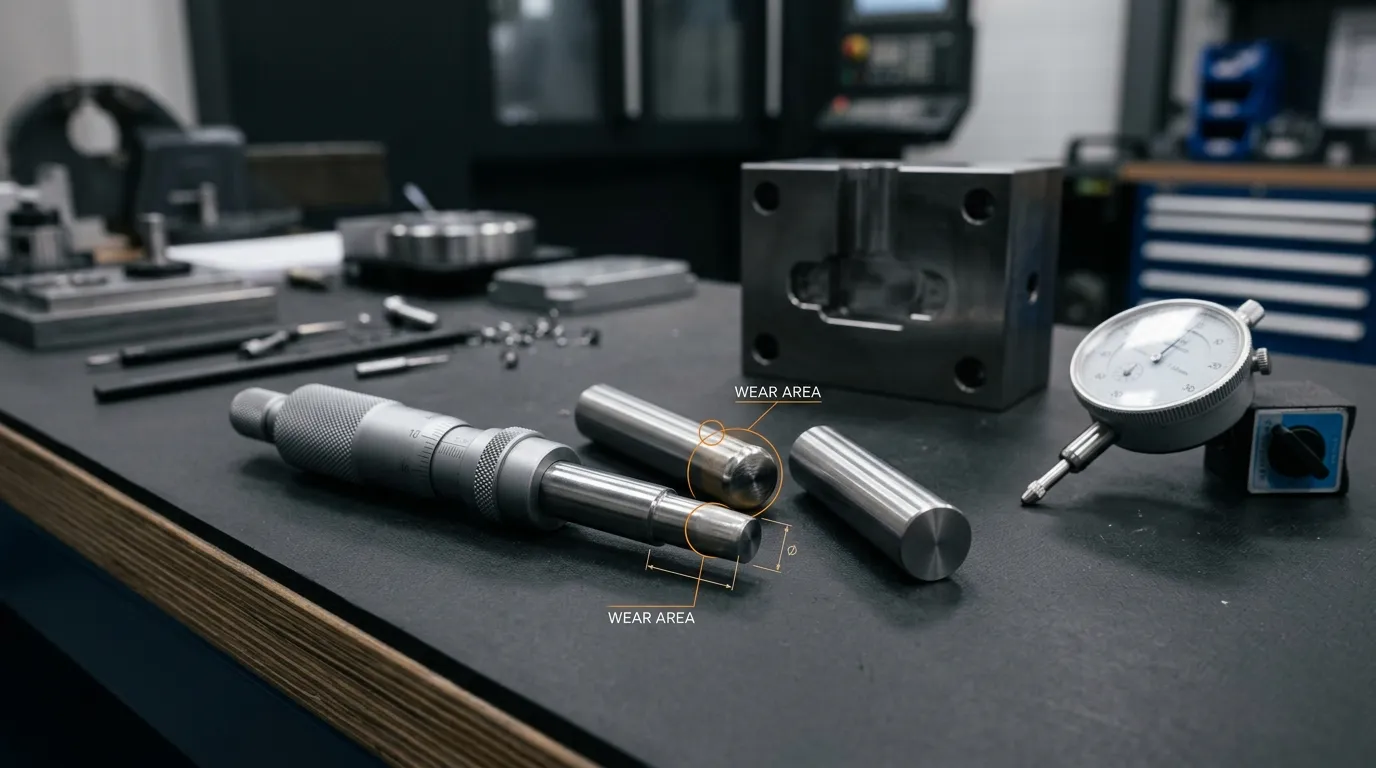
Establish a Safe and Valid Inspection Reference
Before opening, removing, or measuring a limit pin, isolate the molding machine and control all stored energy according to the procedures that apply at the facility. Stored hydraulic pressure, springs, suspended mold sections, gravity, and moving plates can remain hazardous even after the machine has stopped.
For US workplaces, OSHA 29 CFR 1910.147 provides requirements for controlling hazardous energy during servicing and maintenance. Other countries and regions have their own requirements, so the applicable local procedure must control the work.
Before measurement:
- Support the mold and any movable assembly securely.
- Record the pin’s position before removal.
- Photograph visible damage before cleaning it away.
- Remove oil, loose debris, corrosion residue, and dirt from measuring surfaces.
- Check for burrs that could distort the reading.
- Allow the pin and reference equipment to reach a stable measurement condition.
- Confirm which drawing revision or baseline will be used.
Confirm the Pin by Function, Not Name Alone
The terms limit pin, stop pin, and stopper pin may describe similar travel-limiting functions, but naming is not consistent across mold designs and suppliers.
Identify the component by asking:
- Which plate or assembly does it stop?
- Where is its contact face?
- Which surface does it contact at the end of movement?
- Does it carry stopping load, guide movement, return a plate, eject a part, or locate an assembly?
A return pin, ejector pin, guide pin, dowel, or locating pin should not be assessed using a limit-pin procedure simply because it has a similar cylindrical shape.
Choose the Reference Before Taking Measurements
A measured value has little meaning until it is compared with a valid requirement. Use the strongest available reference in this order:
- Controlled component or mold drawing
- OEM specification or approved inspection standard
- Previous approved inspection report
- Qualified new spare
- Historical measurements from the same pin position
- Relative comparison with matching pins from the same assembly
Confirm the units, datum surfaces, tolerances, and drawing revision. A nominal length measured from the wrong shoulder or reference face may produce a precise but useless result.
When a result is close to an acceptance limit, measurement uncertainty also matters. ISO 14253-1:2017 addresses how specification limits and measurement uncertainty affect conformity decisions.
Manufacturing tolerances listed on a supplier’s product page should not automatically be treated as service-wear limits. New-part acceptance and continued-service acceptance are different engineering decisions.
Inspect the Pin and Its Contact System Before Measuring
Begin with a systematic visual examination. Use strong lighting and magnification where needed, but inspect the surrounding components as well as the pin itself.
Check these areas:
- Contact or stop face
- Outer edge of the stop face
- Cylindrical shank
- Diameter transitions
- Shoulder or head
- Thread and retention features
- Seating surface
- Corresponding stop surface in the mold
- Other pins that share the same stopping load
Look for polishing, flattened areas, mushrooming, scoring, metal transfer, pitting, corrosion, cracks, chipped edges, thread damage, and fretting around retained interfaces.
The mating stop surface deserves equal attention. An indentation, burr, embedded particle, or worn pocket can change the functional stopping position even when the pin itself remains close to its original length.
Separate Normal Witness Polishing from Abnormal Damage
A centered and stable polished witness mark may simply show where normal contact occurs. It becomes more concerning when the pattern changes shape, moves toward one edge, or differs significantly between pins in the same set.
| 観察 | Initial interpretation |
|---|---|
| Centered, even polishing | May indicate normal and balanced contact |
| One-sided or diagonal mark | Possible misalignment, unequal height, or side loading |
| Flattened stop face | Repeated impact or concentrated load |
| Mushroomed edge | Plastic deformation at the contact face |
| Longitudinal scoring | Abrasive debris, sliding contact, or misalignment |
| Smeared metal or pickup | Possible galling or adhesive wear |
| Cracks or chipped edges | Structural damage requiring immediate escalation |
| Rust or pitting | Corrosion-related material loss or poor storage conditions |
These observations are clues, not final diagnoses. One-sided wear, for example, may come from a bent pin, unequal pin heights, guide-system wear, a damaged seat, or an uneven mating surface.
Measure Diameter Wear, Taper, and Ovality
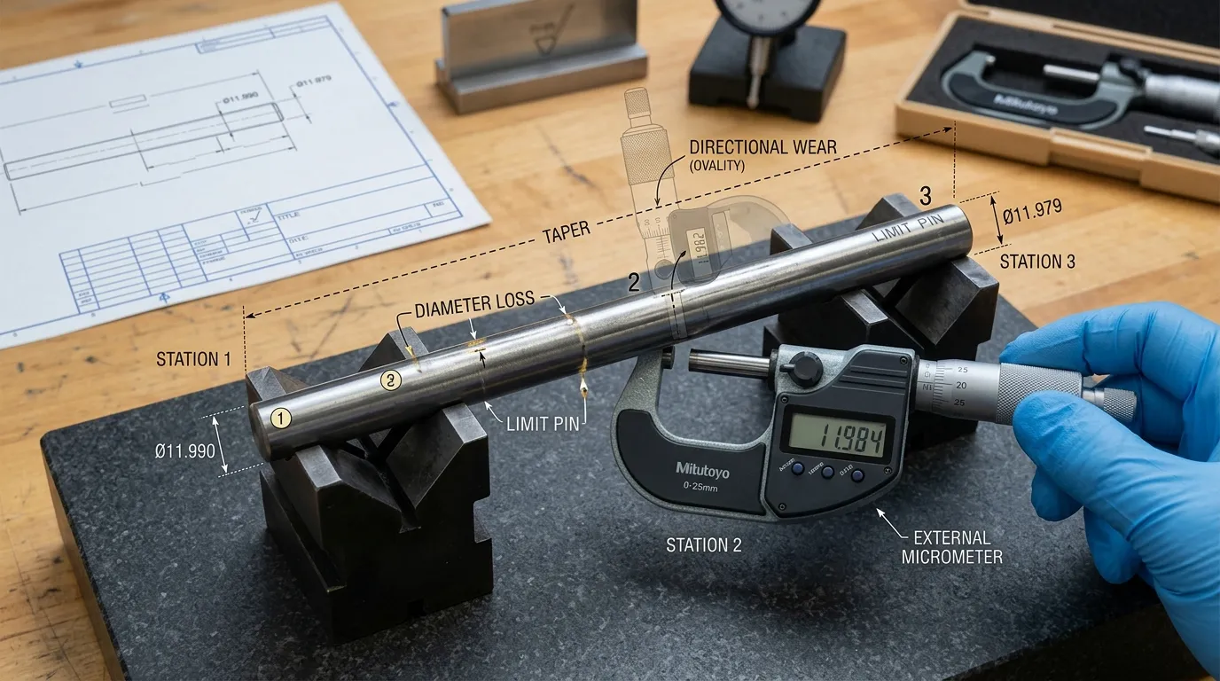
A single diameter reading cannot describe the complete wear condition of a limit pin. Measurements should be taken at repeatable axial locations and in more than one rotational orientation.
An external micrometer is usually more suitable than a caliper when small diameter changes must be evaluated. ISO 3611:2023 defines design and metrological characteristics for external micrometers. Calipers are useful for preliminary checks, but their capability must match the tolerance and expected amount of wear. Their general metrological characteristics are covered by ISO 13385-1:2019.
A practical measurement sequence is:
- Mark the measurement locations along the shank.
- Measure near the upper working area.
- Measure near the centre.
- Measure near the lower working area or seat, where accessible.
- At each location, take readings in at least two rotational orientations.
- Record the position and orientation of every reading.
- Compare the results with the drawing, spare, baseline, and corresponding pins.
This pattern helps separate several conditions:
- Diameter loss: The measured diameter is smaller than the approved reference.
- テーパリング: Diameter changes progressively along the pin’s length.
- Ovality: Readings differ when the pin is rotated at the same axial position.
- Local wear: One short area shows greater loss than the rest of the shank.
Directional diameter loss often supports an investigation into side loading or alignment. Progressive axial wear may indicate contact in a specific working zone rather than uniform material loss.
Do not assign a universal rejection value. The acceptable difference depends on the controlled design, fit, load, and function of the individual mold.
Check Length, Protrusion, and Effective Stop Height
Overall length is not always the most important axial measurement. The functional dimension may be free length, installed protrusion, shoulder-to-face distance, recess depth, or assembled stop height.
First identify the dimension that actually controls plate movement. Then check:
- Overall or free length
- Contact-face deformation
- Installed protrusion
- Shoulder seating
- スレッドの関与
- Seat depth
- Mating-surface condition
- Relative height of matching pins
A pin may measure correctly after removal but still sit too low because of debris under the shoulder, thread damage, seat wear, or an incorrect replacement geometry. The opposite can also occur: the pin may appear shortened when the real loss is an indentation in the opposing stop surface.
Use a height gauge, depth micrometer, height micrometer, or another suitable setup based on the controlled datum and accessibility. The setup must be rigid enough to produce repeatable results.
Compare All Pins That Share the Stopping Load
Several limit pins may work together to stop the same moving plate. Their effective heights should be compared because one high pin can contact first and carry more load than the others.
Check whether:
- Contact patterns appear on all corresponding pins.
- Protrusion or effective height is consistent.
- One pin has a larger polished or deformed area.
- One position shows deeper indentation on the mating surface.
- A previously replaced pin differs from the remaining set.
- One pin contacts before the plate becomes parallel.
Replacing only the visibly damaged pin may not solve the problem if the set has unequal heights or if another component caused the load imbalance.
Check Runout, Bending, and Straightness
A pin subjected to side loading, collision, or severe misalignment may bend without showing major diameter loss.
Where the geometry permits, support the clean pin on suitable datum surfaces or V-blocks and use a dial indicator to measure variation during rotation. Record the indicator position and support arrangement so the test can be repeated.
Before accepting the result, check for:
- Burrs under the support points
- Dirt on the V-blocks
- Damaged cylindrical surfaces
- Irregular shoulders
- Poor indicator alignment
- Excessive measuring force
- Movement of the support fixture
Runout, straightness, and coaxiality are related but not interchangeable terms. ISO 1101:2017 provides the geometrical tolerancing framework for form, orientation, location, and runout. Straightness terminology is further defined in ISO 12780-1:2011.
The total indicated variation from a workshop setup should not automatically be treated as the drawing’s straightness error. It is an inspection result that must be interpreted against the specified geometry and measurement method.
When bending or directional wear is found, inspect the mold’s alignment system. Worn 型ピンとブッシング can allow plate movement that places abnormal side load on a limit pin.
Interpret Wear Patterns Without Jumping to a Root Cause
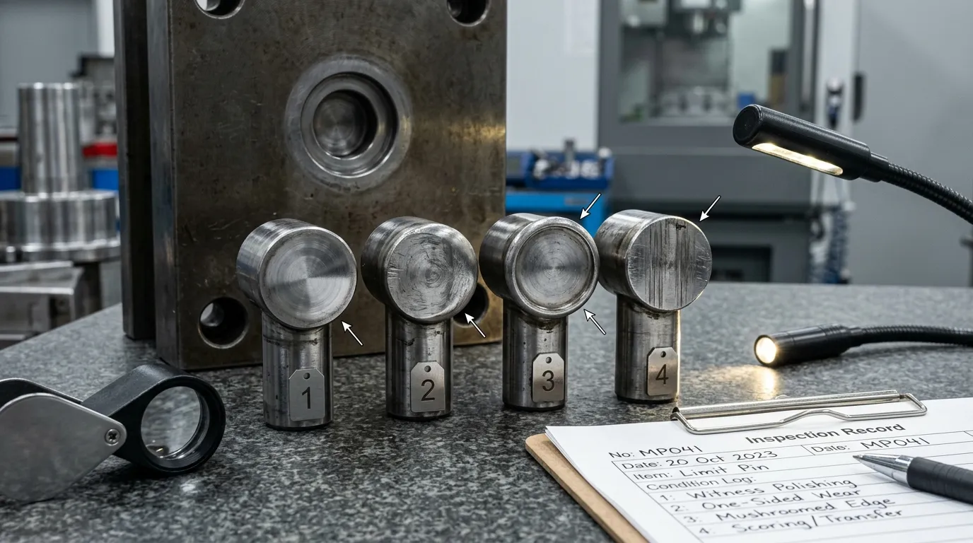
Use each wear pattern to guide further inspection rather than treating it as proof.
| Failure clue | 可能な原因 | Confirmation checks | Immediate response |
| One-sided witness mark | Misalignment, unequal pin height, angled mating surface | Compare matched-pin heights, guide condition, plate parallelism | Continue diagnosis before replacing the pin |
| Flattened or mushroomed face | Repeated impact, overtravel, insufficient contact area, unequal loading | Check effective height, stroke, mating surface, other pins | Measure axial loss and escalate if deformation is active |
| Longitudinal scoring | Debris, abrasive wear, sliding contact, poor alignment | Inspect bore or surrounding surface, contamination, guide system | Remove contamination and assess diameter loss |
| Galling or metal transfer | High friction, adhesive wear, poor surface compatibility | Look for transferred material, heat discoloration, rough mating surface | Stop continued damage and investigate the contact pair |
| Local diameter loss | Concentrated contact or abrasive wear | Map diameter at several axial positions | Compare with drawing and historical data |
| Taper or ovality | Directional wear, side load, uneven support | Rotate measurements, inspect alignment and seating | Determine whether the wear is stable or progressing |
| Excessive runout | Bending, collision, side loading | Repeat indicator setup, inspect guide system and plate movement | Engineering review before reuse |
| Pitting or corrosion | Moisture, chemical exposure, poor storage | Examine nearby components and storage conditions | Assess depth and structural effect |
| Cracks or chipped edges | Impact fatigue, overload, material damage | Inspect with suitable magnification or approved NDT method | Remove from service and escalate |
| Thread or shoulder damage | Loosening, improper seating, repeated movement | Check seat, engagement, retention and installed height | Correct the retention problem before replacement |
Abnormal sound, sticking, plate travel changes, flash, or mismatch can justify an unscheduled inspection. They do not independently prove that the limit pin is the failed component.
Decide Whether to Continue, Monitor, Replace, or Escalate
The final decision should combine dimensional results, visible condition, functional evidence, and the approved acceptance criteria.
| 判決 | Appropriate condition |
| Continue in service | Measurements meet approved criteria, contact is stable, no structural damage is present, and associated components are acceptable |
| Monitor | Minor measurable change is permitted, the condition is stable, and a documented reinspection plan is approved |
| 置き換え | The pin is outside its controlled specification, has unacceptable height variation, severe deformation, damaged retention features, cracking, chipping, or active galling |
| Engineering review | No valid specification exists, results conflict, uncertainty is too high, damage keeps returning, or system-level misalignment is suspected |
A pin should not be polished or reground automatically. Material removal can change its effective length, stop height, contact timing, and load distribution. Serviceability depends on the component’s function and approved dimensional limits.
Generic cycle-count recommendations are also unreliable. Two molds using similar pins may create very different impact loads, alignment conditions, contamination exposure, and maintenance histories.
Record the Inspection and Avoid Common Measurement Errors
A useful inspection record should include:
- Mold identification
- Pin position
- 図面番号と改訂
- Reference used
- Measurement instrument and resolution
- Measurement locations
- Recorded values and units
- Photographs
- Mating-surface condition
- Condition of matching pins
- Relevant operating symptoms
- Final disposition
- Reinspection trigger or approved interval
Consistent records make it possible to see whether wear is stable or accelerating.
Common errors include:
- Measuring through oil, rust, dirt, or burrs
- Measuring a hot component against room-temperature reference data
- Taking only one diameter reading
- Changing measurement locations between inspections
- Using a caliper where greater resolution is required
- Confusing indicated runout with drawing-defined straightness
- Ignoring the seat or mating stop surface
- Comparing pins that are not functionally matched
- Removing damage before photographing it
- Treating new-part manufacturing tolerances as service-wear limits
Broader tolerance, steel, and inspection considerations for 精密金型部品 can support replacement planning, but the used pin must still be judged against its own controlled requirements.
Prepare the Data Needed for a Replacement or Custom Pin
When inspection confirms that a replacement is required, prepare enough information to reproduce the functional geometry rather than sending only the worn component’s current dimensions.
提供:
- Controlled drawing or dimensioned sketch
- Nominal dimensions
- Measured worn dimensions
- Functional stop height
- Contact-face geometry
- Shoulder, head, thread, and seat details
- Material and hardness requirement, where known
- 量
- Matched-set requirements
- Photographs of the pin and mating surface
- Inspection results
- Probable cause of failure
- Required inspection documentation
SunshinePro lists standard and non-standard 型枠リミットピン options, including customization from dimensional requirements. Its published product information identifies S45C/45# steel, precision grinding, threaded construction, vacuum heat treatment, and a stated hardness of 15–17 HRC for that listed product.
Those details are product-specific. They should not be assumed to apply to every existing pin or used as universal replacement criteria.
Replacing the pin without correcting damaged seating, an indented stop surface, unequal matched heights, or alignment problems can cause the new component to fail in the same way. After the cause and required geometry are documented, the drawing, measurements, and photographs can be submitted through SunshinePro’s お問い合わせページ for a standard or custom replacement discussion.


脚本:トンモイ
ニュース
サービスを受けましょう
あらゆる予算に合った高品質な部品と、親切なスタッフが訓練されており、訪問を有益で手間なく提供します。
