



金型の位置決めピンのずれ: 症状とトラブルシューティング
Mold positioning pin misalignment can cause binding during closure, 不均等な接触, parting-line mismatch, フラッシュ, abnormal wear, or inconsistent part dimensions. The pin itself may be damaged, but it is only one possible cause. A worn bushing, loose mounting bore, contaminated parting surface, damaged interlock, 熱成長, poor mold installation, or machine-platen condition can create similar symptoms.
The correct approach is to identify when the problem occurs, inspect the entire mating system, measure the suspected geometry, and repair only the verified cause. For broader information about component fit, 使用期間, 材料, 潤滑, see SunshinePro’s guide to 型ピンとブッシング (推論).
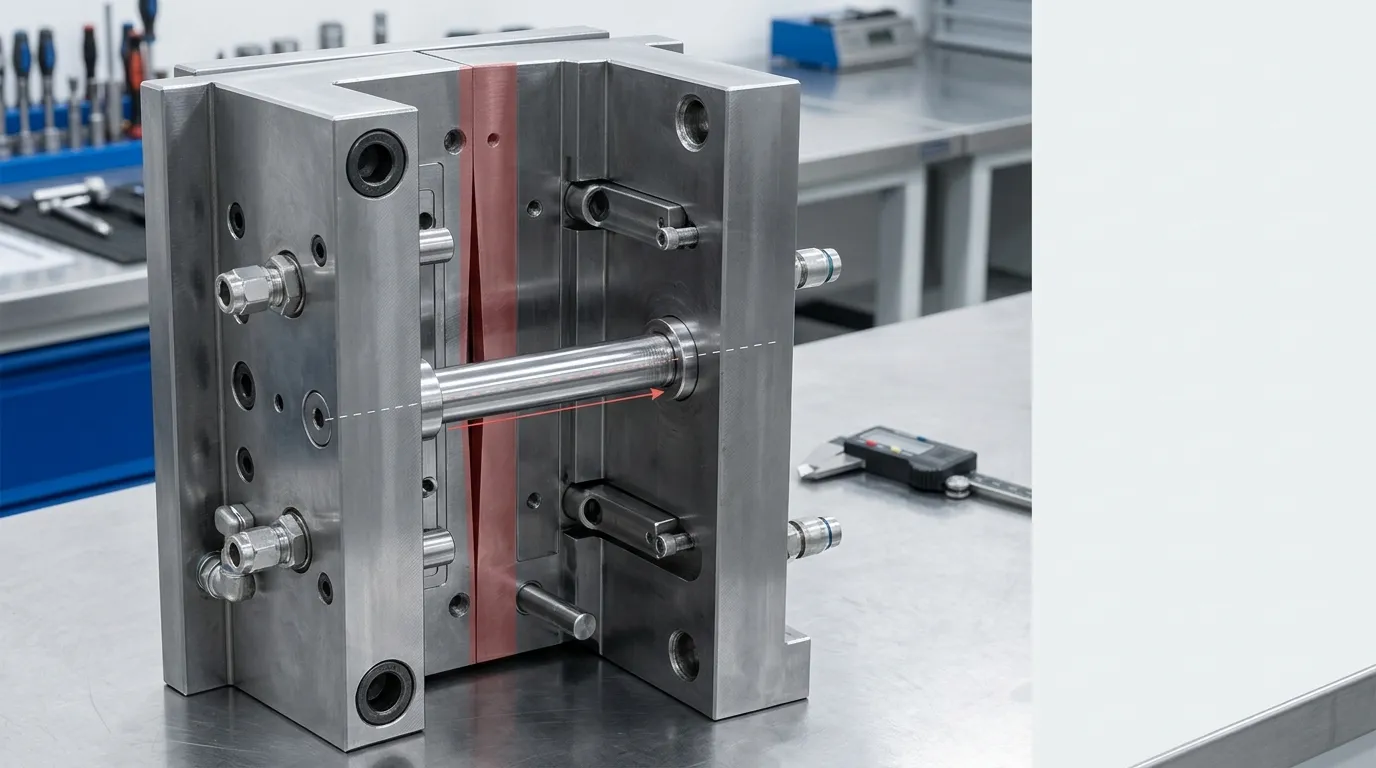
まず、この型の「位置ピン」が何をするのか確認してください
“Positioning pin” is not used consistently across every mold design. Before troubleshooting, identify the component by function rather than relying only on its name.
| 構成要素 | 主な役割 | 診断上の示唆 |
|---|---|---|
| 位置定またはダボピン | 部品や板間で繰り返し可能な位置を確立します | Check its geometry, 取り付けフィット, 向き, and mating hole or bushing |
| ガイドピン, leader pin, またはガイドピラー | 接合時に型の半分を導きます | まっすぐさを確認してください, 使用期間, bushing clearance, and side-loading marks |
| ブッシングのガイドまたは位置付け | ピンを受け取り、マッチングインターフェースを制御します | Check bore wear, ovality, ポジション, 保持, and entry damage |
| サイドインターロックまたはテーパーロック | 最終的なカビ登録の確立や維持に役立ちます | Check contact pattern, 使用期間, 損傷, そして関与 |
| シャットオフまたは精密結合面 | 最終的なアライメントとシーリングに寄与します | Check for impact marks, ミスマッチ, local gaps, and edge damage |
A guide pin may control the initial closure path while another locating feature controls final core-to-cavity registration. Replacing the guide pin will not solve the problem if the final interlock, ブッシング, mounting bore, or mold plate is out of position.
SunshineProの別個ガイド 型ガイドピン covers broader guide-pin function, 使用期間, そして選択. はい, the focus is determining why an installed mold is no longer aligning correctly.
カビ登録の問題を示す症状
The timing and location of a symptom often provide more useful evidence than the symptom alone.
| 症状 | 現れるとき | 可能なサブシステム | 最初の確認確認 |
| 閉鎖時の同じ地点でのバインディング | コールドクロージャーまたはノーロードクロージャー | 曲げられたピン, skewed bushing, damaged interlock, バー, or plate-position error | 最初の接触点で立ち止まり、片側の目撃者痕がないか確認してください |
| Scraping, 振動, or impact noise | ピンまたはインターロックの交差時に | サイドローディング, insufficient clearance, 汚染, or damaged entry geometry | Inspect the pin, bushing mouth, インターロック, and nearby surfaces |
| ガイド系付近の異常な熱 | 繰り返しのサイクリングの後 | 摩擦, 潤滑不良, tight fit, サイドローディング, or galling | スコアを確認しましょう, 変色, 潤滑剤の状態, and uneven contact |
| カビは完全に閉じません | セットアップまたは制御されたクロージング | Mounting error, 障害, プレート歪み, machine-side alignment, or damaged positioning components | Inspect mounting, 位置特定機能, parting surfaces, and plate relationships |
| パーティングラインステップまたはミスマッチ | 制作中 | Registration loss, プレートの動き, interlock wear, or machine-side loading | ミスマッチの位置と接触や摩耗パターンを比較してください |
| 局所フラッシュ | 注入圧下 | Misregistration, damaged shutoff, insufficient clamping, 汚染, or process conditions | 金型が圧力なしで合っているか、影響を受けた遮断装置も点検してください |
| サイクル間の次元変動 | ウォームアップ後や負荷下 | Changing clearance, 熱成長, プレートの動き, or worn positioning features | Compare cold, warm, and production-condition measurements |
| 片面ピンまたはブッシング研磨 | 時間とともに進行 | Mispositioned bore, bent pin, plate error, or uneven machine loading | ピンのランアウトを測定し、ボアの位置と垂直性を検査します |
DME’s technical guidance on mold interlocks identifies flash, dimensional problems, and component damage as possible consequences of improper mold alignment. It also notes that worn leader pins and bushings, thermal variation, mold weight, and equipment condition can affect registration. See DME’s 型の整列技術指導.
Flash alone does not prove positioning pin failure. Flash can also result from damaged shutoffs, trapped material, insufficient clamping, 過剰な圧力, or other tooling and process conditions. Treat it as evidence that requires further inspection.
カビ閉鎖時の症状
Closure-related symptoms usually point toward the engagement path.
探してみて:
- Resistance that begins at the same position during each closing attempt.
- A pin entering the bushing off-center.
- Fresh contact marks on only one side of the pin.
- Scraping at the bushing entrance.
- Impact marks on interlocks or shutoffs.
- A visible gap on one side of the parting line.
- A pin, ブッシング, or retainer moving in its mounting feature.
A repeatable hard-contact point is more likely to involve geometry, 障害, or mounting position than a process-setting problem.
型取り部分や分離面の症状
Production evidence may include:
- A step across the parting line.
- Flash concentrated in one region.
- Uneven witness lines.
- Chipping or peening near a precision shutoff.
- Dimensional changes after the mold reaches operating temperature.
- Parts that shift in one direction under pressure but appear acceptable during an unloaded closure check.
These symptoms help locate the affected region, but measurements are still needed before deciding which component to repair.
損傷が起こりそうな場合は、カビのサイクルをやめましょう
Do not continue closing the mold to “see if it clears” when there is evidence of hard interference or displaced components.
Stop and establish a safe inspection condition when you find:
- A visibly bent or loose pin.
- A cracked, 欠けている, or displaced bushing.
- Metal fragments or severe scoring.
- Fresh impact damage on a core, 空洞, 挿入, shutoff, or interlock.
- Sudden hard resistance during closure.
- A plate or component moving inside its mounting feature.
- An engagement path that cannot be confirmed safely.
Injection molding machines can expose technicians to crushing, stored hydraulic energy, electrical energy, hot surfaces, and moving components. Inspection and servicing should follow the machine manufacturer’s instructions, the facility’s hazardous-energy procedure, and applicable local regulations. アメリカ合衆国. Occupational Safety and Health Administration provides general guidance on 水平射出成形機の危険性 そして 有害エネルギーの制御.
固定順序でのずれのトラブルシューティング
A consistent sequence reduces unnecessary disassembly and prevents one symptom from being mistaken for proof of pin failure.
- Review when the problem started.
Determine whether the change was sudden or progressive. Check whether it began after maintenance, 部品交換, mold transfer, machine setup, a cooling change, or warm-up. - Place the machine and mold in an approved safe inspection condition.
Isolate hazardous energy before entering the mold area or touching components that could move. - Clean exposed interfaces.
Remove trapped plastic, チップス, バー, contaminated lubricant, and other debris from the parting line, pin entries, ブッシング, and interlocks. - Inspect the pin, ブッシング, 取り付け, そして保持.
Look for looseness, 得点, impact marks, 不均一な研磨, 移動, or damaged fasteners. - Observe the engagement pattern.
Under an approved controlled procedure, identify which component contacts first and whether the contact is centered or one-sided. - Measure the suspected geometry.
Check pin and bushing dimensions, ランアウト, 取り付けボア条件, component position, and plate relationships. - Separate mold-side causes from machine-side and thermal causes.
Compare cold and warm behavior, unloaded and production-loaded behavior, and results across machines when practical. - Correct the verified cause.
きれいだ, adjust, 修理, or replace only after the inspection evidence supports that action. - Validate the repair.
Confirm smooth engagement, stable registration, correct parting-line contact, and acceptable molded-part results.
問題が始まった時の記録
The failure history can quickly narrow the investigation.
A sudden problem after maintenance may indicate:
- A reversed or incorrect replacement component.
- A bushing or pin installed at the wrong depth.
- A burr created during assembly.
- A loose retainer or fastener.
- A plate assembled out of position.
Progressive deterioration more often suggests:
- Increasing pin or bushing wear.
- Lubrication breakdown.
- Mounting-bore damage.
- Plate movement.
- Repeated side loading.
- Thermal or machine conditions that gradually accelerate wear.
A problem that appears only after moving the mold to another machine should trigger checks of mold installation, locating-ring engagement, platen condition, and clamping alignment before replacing mold components.
まずは清掃と非破壊検査から始めましょう
Begin with checks that do not alter the mold:
- Clean pin surfaces and bushing entrances.
- Remove plastic residue from the parting line.
- Inspect for burrs around bores and interlocks.
- Check retainers and fasteners for movement.
- Mark and photograph contact patterns.
- Compare the left and right sides of the mold.
- Check whether the pin enters the bushing concentrically.
Cleaning may restore movement when debris is the only obstruction. It does not prove that the pin, ブッシング, or plate geometry remains within specification.
ピンを点検する, ブッシング, and Mounting Features as One System
A positioning pin does not work independently. Its performance depends on the mating bushing or hole, the mounting bore, the mold plate, and any final-positioning features.
ピン側破損の手がかり
Evidence that directly implicates the pin includes:
- Measurable bending or runout.
- One-sided scoring along the engagement length.
- Impact damage at the leading end.
- Mushrooming or chipped edges.
- A loose shank or failed retaining feature.
- Incorrect installed height.
- Geometry that does not match the drawing.
- Contact concentrated in one region rather than distributed as intended.
One-sided polishing can indicate a bent pin, but it can also result from a mispositioned bushing or mounting bore. Confirm the pin’s straightness before assigning the cause.
ブッシング- and Bore-Side Failure Clues
Inspect the mating side for:
- Uneven or oval bore wear.
- A loose bushing.
- Damage at the entry chamfer.
- Scoring concentrated on one side.
- A bushing installed out of position.
- Cracks or deformation around the mounting feature.
- A damaged press-fit bore.
- Burrs that prevent the bushing from seating correctly.
Replacing a worn pin while leaving an oval or loose bushing in place may restore movement temporarily without restoring repeatable registration. The mating pair and both mounting features should be evaluated together.
修理を選ぶ前にジオメトリを測定してください
Visual inspection identifies where to investigate, but dimensional evidence should determine whether a component is acceptable.
Measure as applicable:
| 特徴 | なぜ重要なのか | 受け入れ基準 |
| 複数の位置におけるピンの直径 | Reveals taper, localized wear, or material loss | 承認された型設計図または部品仕様 |
| ブッシングは複数の方向でボアを開けました | 過剰なクリアランスや楕円形の摩耗を特定する | ドローイング, supplier specification, or applicable standard |
| ピンの直線性またはランアウト | 進行性の側面接触を引き起こす曲げを検出します | 図面または承認された検査手順 |
| ピンとブッシングの位置 | 軸が揃うかどうかを決定します | 型の図面と基準面構造 |
| プレートに対する垂直性 | 傾斜した取り付けやボアエラーの特定 | 図面または工学仕様 |
| 取り付けボア条件 | コンポーネントが正しく支えられ、保持されているかどうかを判断します | 図面と承認された修理基準 |
| プレート関係 | Detects shift, 歪み, or movement between assemblies | 型組立図面および検査計画 |
Do not apply one universal pin-to-bushing clearance or wear limit to every mold. The correct value depends on the component design, サイズ, 機能, supplier series, 動作温度, and required positioning accuracy.
For standardized components within their stated scope, ISO 8017 covers dimensions and tolerances for specified guide pillars and locating guide pillars. ISO 8018 covers specified headed guide and locating guide bushes. These standards do not replace the approved mold drawing, and they should not be applied to components outside their scope.
Record the measurement reference, 楽器, セットアップ, 図面の改訂, and actual results. A list of numbers without the measurement method may not be sufficient for repair or replacement decisions.
金型側の原因と機械や温度の影響は別個です
The same mold symptom can originate outside the pin-and-bushing pair.
Ask:
- Did the problem begin after installing the mold on a different machine?
- Does the mold align when cold but bind after warm-up?
- Does it close smoothly without pressure but shift during production?
- Is one mold half operating at a different temperature?
- Are the locating ring and mounting surfaces seated correctly?
- Are the platens, クランプ, or tie system applying uneven load?
- Do interlocks show contact only after pressure is applied?
- Does the problem disappear when the mold is checked outside the original machine?
冷たい時と熱時のずれ
A mold may close correctly at room temperature and begin binding after thermal stabilization. Unequal heating changes the dimensions of plates, bores, ピン, ブッシング, and interlocks. The pin may appear to be the problem even though the underlying cause is differential thermal growth.
Compare:
- Cold engagement.
- Engagement during warm-up.
- Stable operating-temperature engagement.
- Temperatures on both mold halves.
- Cooling conditions near the affected region.
- Contact marks before and after warm-up.
Do not assume the pin changes independently of the surrounding plate. The entire alignment chain expands and moves together.
無負荷と加圧時のずれ
Smooth unloaded closure does not guarantee stable registration during production.
If misalignment appears only under injection or clamping load, 検査:
- Side interlocks and taper locks.
- Plate support and fasteners.
- Shutoff contact.
- Mold mounting.
- Platen condition.
- Locating-ring engagement.
- Load-sensitive movement between plates.
Changing pressure, 速度, or clamping settings may reduce the visible defect, but it does not correct a mechanical positioning error.
是正措置を確認原因に合わせる
| 原因確認 | 適切な措置 | 追加チェック |
| Trapped plastic, チップス, or removable debris | 影響を受けた表面を清掃してください | バリや永久的な損傷がないか確認してください |
| 汚染または承認された潤滑剤の欠落 | 指定された潤滑状態を清掃し、修復してください | Inspect for existing scoring, 使用期間, or galling |
| Bent, worn, or impact-damaged pin | 承認された図面に合致する部品に交換してください | ブッシュと取り付けボアを点検してください |
| 摩耗または楕円形ブッシュ | 型の設計に応じて交換または修理してください | ピンの状態と実際の結合クリアランスを確認してください |
| ピンやブッシングが緩んでいる | 固定または取り付けの機能を、認可された修理によって修正してください | ボアやプレートが損傷していないか確認してください |
| 損傷した取り付けボア | 新しい部品を取り付ける前に、ボアや影響を受けたプレートを修理してください | 位置と垂直性の再確立 |
| 摩耗したインターロックまたは遮断 | 影響を受けた最終位置付け機能の修理または交換 | ガイド部品がサイドロードされていないか確認してください |
| 設置または位置リングエラー | 正しい型の取り付けとセンタリング | 閉鎖と離別線接触の再確認 |
| 機械側のローディングやプラテンの問題 | 機械製造者の検査と修理のプロセスを守ってください | カビが二次的な被害を受けていないか確認してください |
| 熱歪み | 検証済みの温度や冷却の不均衡を修正してください | 安定した動作温度でのアライメントの検証 |
Lubrication can reduce friction. It cannot straighten a bent pin, correct a misplaced bore, restore an oval bushing, or realign a distorted plate.
Do not install a new pin into a damaged bore simply because the replacement fits initially. If the mounting feature cannot hold the component at the required position and angle, the new part may fail quickly or reproduce the same alignment error.
型を生産に戻す前にアライメントの検証を行ってください
After correction, validate the complete system rather than checking only whether the mold can close once.
Use the machine manufacturer’s approved procedure to confirm:
- Smooth and repeatable engagement.
- No abnormal impact, scraping, 振動, or resistance.
- No new scoring or concentrated witness marks.
- Correct parting-line and shutoff contact.
- Stable pin and bushing temperatures.
- No movement at retainers or mounting features.
- Consistent behavior after the mold reaches operating temperature.
- Stable registration under approved production conditions.
- Acceptable molded-part dimensions.
- No abnormal flash or parting-line step.
Recheck critical dimensions when a pin, ブッシング, ボア, プレート, or interlock has been repaired. Record what was changed, the measurements taken, and the validation result. One successful closing cycle is not sufficient evidence of long-term correction.
部品が仕様外の場合、完全な交換情報を作成してください
Once inspection confirms that a positioning pin, guide component, or bushing requires replacement, provide the supplier with enough information to reproduce the intended geometry rather than the worn condition.
準備:
- The approved component drawing and revision.
- The component’s function: 位置づけ, ガイド, or final positioning.
- Pin and mating-bushing dimensions.
- Mounting and retention details.
- Required fit and tolerances.
- 材料, 硬度, 熱処理, and surface requirements stated on the drawing.
- 量.
- The worn sample, when useful and available.
- Photographs or notes showing the failure pattern.
- Confirmation of whether the mating component or mounting bore will also be repaired.
- Required inspection documentation.
SunshineProは標準および図面ベースのカスタムを提供していると述べています 金型標準部品, including guide components and dowel pins. The company also lists locating-pin guide bushings and describes inspection processes for custom components.
After the failed component and its mating conditions have been measured, the next practical step is to 図面と交換要件を提出してください for review. The request should describe the verified failure and required geometry rather than asking a supplier to reproduce an unmeasured worn sample.



サンシャインより書かれました
サンシャインで, 私たちは精密金型部品の専門製造およびサプライヤーです, プレスおよび射出成形用途向けの幅広い製品を提供しています. 私たちの主な焦点はパンチダイスです, イジェクターピンとスリーブ, ガイドポストとブッシング. 高度なCNC加工技術で, 厳格な品質管理, そして強力な生産能力, 私たちは信頼性を保証しています, 高精度部品, また、迅速かつ効率的なグローバル供給のための在庫の標準部品も併用しています.
ニュース
サービスを受けましょう
あらゆる予算に合った高品質な部品と、親切なスタッフが訓練されていて、訪問を有益で手間なく充実させてくれます.
