



繰り返しの小穴パターンのための穿孔パンチピン設計
Perforation punch pin design is not simply a matter of choosing a small diameter and a hard material. A reliable design must coordinate the hole pattern, sheet material, パンチジオメトリ, support system, combined cutting force, クリアランス, slug path, and maintenance method.
The challenge becomes greater as hole diameter decreases or more holes are punched during each stroke. 長い, unsupported tip may deflect. A dense cluster can exceed press capacity or distort the sheet. Small slugs may clog the die or return to the work surface. The punch therefore has to be designed as part of the complete cutting system.
パンチに関するより広い情報, stripper systems, guide elements, and other tooling parts, 参照 ダイ部品ガイド (推論). This guide focuses specifically on punch pins used for repeated small-hole patterns.
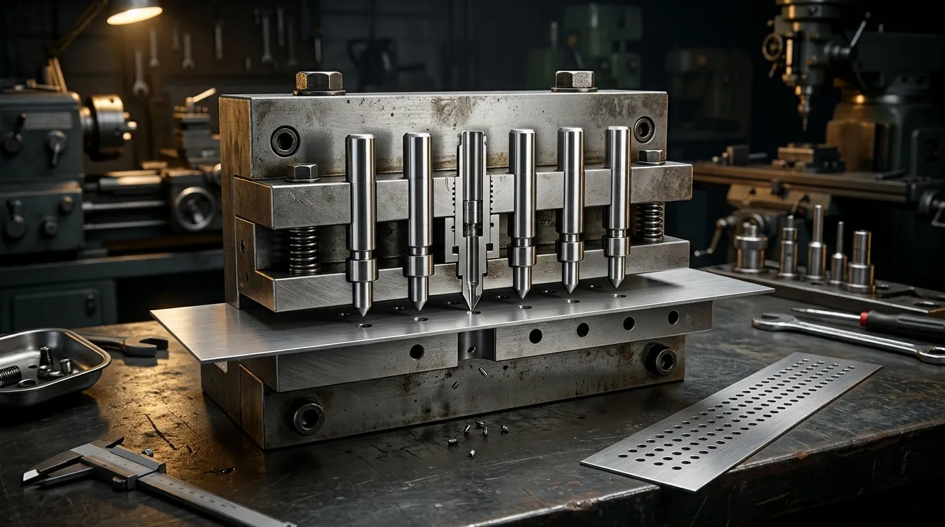
What Must Be Designed Together in a Perforation Punching System?
A perforation punch pin forms one part of a load path that extends through the tool:
- The cutting tip enters the sheet.
- The punch shank transfers the cutting load upward.
- The punch plate locates and retains the pin.
- The backing plate supports the punch against axial reaction.
- The stripper controls the sheet and may guide the punch near its tip.
- The die opening provides the opposing cutting edge.
- The slug passes through the die relief and exits the tool.
A weakness in any one part can affect the entire operation. A strong punch material will not prevent failure if the working tip is too long, the stripper allows lateral movement, or the die opening is misaligned. A correctly sized pin can still produce unstable results if several tips create excessive combined force or if the slug path becomes blocked.
This is why perforation tooling should not be treated as an isolated component-selection exercise. General die construction and die-type decisions are covered more broadly in the パンチダイズガイド. はい, the design starts with the repeated hole pattern and works inward toward the punch pin.
ピン設計前に穴のパターンとシートの要件を定義してください
The working diameter is only one input. Before selecting a pin architecture or material, define the conditions that control the cutting operation.
The design package should include:
- シートの素材と状態
- 公称シート厚と厚さ公差
- Hole diameter, 形状, and dimensional tolerance
- 各方向のホールピッチ
- 隣接する穴の間に残る物質
- Pattern arrangement, including aligned or staggered rows
- 必須の開放スペース
- バリの方向と許容バリ高さ
- シートフラットネスの要件
- Expected production volume
- 利用可能な報道・放送局の収容人数
- 潤滑と清潔性の要件
- 計画された研ぎと交換方法
These inputs are connected. Changing the sheet thickness affects cutting force, slug geometry, practical hole size, and die clearance. Reducing hole pitch leaves less material between adjacent openings and may weaken both the sheet and the die. Increasing the number of tips raises the combined cut perimeter and total force.
Hole Size, 材料, and Thickness Set the First Feasibility Check
A small hole is more difficult to punch when its diameter approaches or falls below the sheet thickness. The exact practical limit depends on the work material, punch material, ガイダンス, アラインメント, tool construction, and required hole quality.
A hard or high-strength sheet generally creates greater cutting load than a softer material of the same thickness. A small punch cross-section must carry that load without bending, 欠け声, or breaking. Guided tooling may support a more demanding diameter-to-thickness relationship than a long, non-guided punch, but guidance does not eliminate the need for sufficient punch strength.
MISUMIのガイダンスなどの技術的参考文献 小径穴開き emphasize short working sections, stepped support, and controlled slug removal. Supplier ratios can be useful for an early feasibility check, but they should not be treated as universal design limits.
Pitch, Remaining Web, and Flatness Define the Pattern-Level Risk
Hole pitch is the centre-to-centre distance between adjacent perforations. The remaining web, sometimes called the bridge, is the material left between their edges.
A pattern may contain individually feasible holes but still be difficult to manufacture if the web becomes too narrow. Dense perforations can:
- 局所的なシート剛性の低減
- 開口部間の金型材料を弱めてください
- ホール相互作用のリスクを高める
- シートの伸縮や波打つ感を生み出します
- 大きなパネルに油缶を作ってください
- 切削荷重を工具の一箇所に集中させます
Aligned rows and staggered rows do not distribute load in the same way. A staggered pattern may improve open-area distribution or reduce direct alignment of weak sections, but it does not automatically solve distortion. The finished panel’s flatness requirement must be considered with the complete punching sequence.
小さな作業用チップをサポートするパンチピンのアーキテクチャを選びましょう
A perforation pin normally contains several functional regions:
- 穴を作る作業先端
- 先端の後ろにトランジションや肩が
- 荷重を移動し支えるより大きなシャンク
- パンチプレート内にパンチを位置づける保持機能
- 必要に応じて調整や再研磨の許容度も提供します
The small working portion should be only as long as the operation needs. Extra unsupported length increases sensitivity to lateral movement and bending. The required length must still allow suitable penetration, stripper guidance, withdrawal, and future sharpening.
まっすぐ, Stepped, and Multi-Step Pins Serve Different Section Sizes
| ピンアーキテクチャ | 典型的な設計ロジック | 主な利点 | 主な制限 |
|---|---|---|---|
| ストレートピン | 作業部とシャンクは同じまたは類似の断面を持つ | 単純な形状と製造 | 非常に小さな全長断面では剛性が欠けることがあります |
| ステップドピン | 小さな作業先端はより大きなシャンクで支えられています | 切断部の裏側のより良いサポート | 肩の位置とトランジションは慎重な設計が必要です |
| 多段ピン | いくつかのトランジションが小さな先端からはるかに大きな本体へつながっています | 大きく異なるセクション間のより緩やかな変化 | より複雑な形状と検査 |
三隅の議論 穴あけパンチの設計 distinguishes straight, ステップド, and multi-step punches according to the strength and size of the functional section.
A stepped punch is often considered when the required hole is too small for a long straight pin to remain sufficiently rigid. The larger shank provides support, while the smaller section performs the cut. The transition should transfer load without creating an unnecessarily sharp stress concentration.
作業長と遷移形状の制御、たわみと応力
Two punches with the same tip diameter can behave very differently if one has a much longer unsupported working section.
As the slender section becomes longer, the pin becomes more vulnerable to:
- 横方向のたわみ
- 金型開口部とのずれ
- 側面摩耗の不均一さ
- 切断先端の欠け
- 疲労破壊
- ストリッピング中の曲がり
The transition behind the working tip also matters. An abrupt reduction in section can create a highly stressed area. A better-supported transition distributes the load into the larger shank while preserving the required access to the sheet and stripper.
There is no single universal working-length ratio for every material and application. The final geometry must account for penetration, シート厚, stripper position, guidance length, 再研磨手当, and the actual load on the tip.
Guide, 保持, and Back the Punch Through the Full Stroke
Small punches require both axial and lateral support.
The punch plate retains and locates the shank. The backing plate supports the punch against cutting reaction. The stripper controls the sheet during withdrawal and may guide the punch close to the cutting region. These elements must remain aligned with the die opening.
Even a correctly dimensioned pin can fail if the support system allows side loading.
ストリッパーガイダンスが切断先端付近のパンチの徘徊を制限する
A stripper-guided punch passes through a controlled opening in the stripper plate before entering the sheet. This close support reduces the distance over which the small tip can move laterally.
三隅の技術ノート 穴のブランキングパンチ用のストリッパーガイダンス explains that small punches are especially vulnerable to lateral movement. The stripper can reduce that movement, but only when the stripper itself moves accurately.
If the stripper tilts, shifts, or has excessive clearance, it may transfer error to the punch rather than correcting it. The stripper opening, punch shank, and die opening must therefore be treated as one alignment system.
パンチプレートとバックプレートが軸方向荷重経路を完成させます
The punch plate positions the pin, but it may not provide sufficient resistance to concentrated axial load by itself. A small punch head or shank can create high local pressure behind the pin.
A backing plate spreads this reaction into a stronger supporting area. Without adequate backing, the punch may indent or sink into the holder, changing its working height and alignment.
三隅の指導 裏板設計 highlights this issue for punches with small supporting cross-sections.
The load path should remain flat, rigid, and correctly located. A hard punch placed against a weak or poorly supported holder can still lose position under repeated loading.
ピンの数とパターン配置を利用可能なパンチ力に合わせます
A cluster punch produces several holes in one stroke. This can reduce the number of press cycles required, but the press must cut the combined perimeter of all engaged tips.
The total load is not determined by hole count alone. It depends on:
- 交戦した切断周囲の総攻撃距離
- シート厚
- 加工材料とせん断抵抗
- 同時に切断する先端の数
- パンチの鋭さ
- クリアランス
- ストリッピング条件
- 工具およびプレス効率
Adding more tips may increase output per stroke, but it also raises cutting load, slug volume, maintenance exposure, and the possibility of sheet distortion.
Estimate Force from Total Cut Perimeter, Not Hole Count Alone
A conceptual punching-force relationship is:
パンチング力≈切削周長×シート厚×材料のせん断抵抗
For a cluster, the total cut perimeter is the sum of the perimeters of all tips engaged during the same part of the stroke.
This means ten small round holes do not create the same load as ten slots with a much greater combined perimeter. Two patterns with similar open area may also require different force because their edge lengths differ.
メイト・プレシジョンズ クラスターパンチング誘導 uses total cutting perimeter as a central force-planning factor and recommends checking cluster load against the machine and station limits.
The calculation should be treated as an engineering estimate. The actual tool must also account for stripping force, load balance, 報道状況, and the manufacturer’s tooling limits.
段階的処理や負荷分散はパターンレベルの問題を軽減できます
If every adjacent tip enters the material at the same time, cutting load may be concentrated within a small area. This can increase peak force and stretch the sheet around the pattern.
Possible design responses include:
- パターンを複数のステーションに分割する
- アクティブチップを減らすこと
- 関与が分散するように列を配置する
- 金型システムが許す範囲で先端の長さをずらして配置します
- ツールセンター周辺のパターンのバランス調整
- パンチングシーケンスの変更
These methods can reduce local concentration, but they may also add tool complexity or change the loading sequence. They must preserve the finished hole locations and part geometry.
ウィルソンツールの情報 クラスターツールによる穿孔 also identifies sheet stretch and oil-canning as practical concerns in dense perforation work.
ダイクリアランスとスラッグ排出の調整
The punch and die opening form one cutting pair. Clearance between them influences cutting load, fracture behaviour, バー形成, 工具の摩耗, and slug release.
Repeated small-hole patterns make waste handling especially important. A cluster with 20 tips creates 20 slugs during each complete punching cycle. Even when each slug is small, the cumulative waste flow can become substantial.
The die must provide:
- 適切な切削クリアランス
- 国に十分な条件を
- 切断先端下のリリーフ
- 連続した出口ルート
- 検査と清掃のためのアクセス
- スラッグ再循環からの保護
Clearance Must Be Verified for the Material, 厚さ, and Required Edge
Clearance is normally considered per side between the punch and die cutting edges. The appropriate value depends on the sheet material, 厚さ, required edge condition, punch condition, and tooling method.
Clearance that is too small may increase force and wear. Clearance that is too large may increase burrs, edge rollover, または次元変動. As the punch and die wear, effective clearance changes even if the original dimensions remain correct.
For this article, the important point is that the pin diameter cannot be finalized independently from the die opening. Exact clearance values require material- and application-specific calculation and validation.
穴が増えるごとに、確実に排出しなければならないスラッグが1つ増えます
Small slugs can:
- 制限されたダイス通路に蓄積
- 狭い地形区間を渡る橋
- 詰まりに圧縮する
- パンチフェイスに忠実に
- 作業台への復帰
- 後のストロークでシートを損傷する
The die relief should allow slugs to move away without trapping one another. Tool access should permit cleaning before debris raises the cutting load or damages the punch.
Slug pulling requires particular attention. A slug that follows the punch upward may be pressed back into the sheet or trapped between the tool and workpiece. 幾何学, クリアランス, 潤滑, 表面状態, and waste-path design can all influence this behaviour.
予想される破壊モードによるピン材料と表面処理の選択
The hardest available punch material is not automatically the best choice. Material selection should respond to the dominant failure risk.
Common risks include:
- 研磨摩耗
- 接着による摩耗や擦り傷
- エッジチッピング
- 疲労破壊
- 塑性変形
- ずれによる影響
- 腐食や表面損傷
A material that resists wear well may be less tolerant of shock or side loading. A tougher material may survive misalignment better but require more frequent sharpening.
ツールスチール, HSS, and Carbide Balance Wear and Toughness Differently
| 物質的家族 | 有用な特徴 | 主な設計上の懸念 |
| Tool steel | Broad balance of toughness, 耐摩耗性, 熱処理, and regrindability | 性能はグレードや熱処理に大きく依存します |
| 高速鋼または粉末冶金鋼 | 耐久性を保ちつつ、耐摩耗性を高めることができます | コストや加工の難易度が増加する可能性があります |
| Carbide | 高い耐摩耗性と圧縮強度 | 衝撃に対してより敏感です, 欠け声, and alignment errors |
Carbide may be suitable for stable, 研磨性, high-volume applications, but it is not a universal solution for every small hole. A slender carbide tip exposed to side load or impact may chip where a tougher steel punch would survive.
The selection should consider the sheet material, working-tip diameter, 支えのない長さ, ガイダンス, 潤滑, 報道状況, and previous failure history.
サンシャインプロズ カスタムパンチピン ページにはSKH51が記載されています, SKH9, DC53, ASP-grade materials, and carbide among its stated material options. Final suitability still has to be confirmed against the actual drawing and application.
表面仕上げ, コーティング, and Lubrication Address Surface Interaction
Surface finish influences friction, 素材の収集, リリース, and the condition of the substrate beneath a coating. A smoother working surface may help reduce adhesion in suitable applications, but finish alone cannot correct an unsupported tip or misaligned die.
Coatings such as TiN, TiCN, and DLC may be considered for selected wear or friction conditions. Their value depends on:
- パンチ基板
- ワークピース素材
- 表面準備
- エッジジオメトリ
- 潤滑
- 温度
- 衝撃と側面荷重
- コーティングの接着
A coating should not be used as a structural repair. It cannot compensate for excessive working length, poor stripper guidance, weak backing, or incorrect clearance.
Lubrication is also part of the system. It can reduce friction, 接着性摩耗, and stripping resistance, but the lubricant must be compatible with the work material, downstream process, and cleanliness requirements.
Design the Tool for Replacement, 研ぎ, and Inspection
Perforation tooling should be serviceable before the first production run begins. A design that performs well initially but cannot be repaired economically may create unnecessary downtime later.
The maintenance plan should address:
- 個別のピン交換
- スペアチップの入手可能性
- 研ぎ換量
- 再研磨後の長さ調整
- 保持されたピンへのアクセス
- 先端の識別
- 検査ポイント
- 代替制限
固定式マルチチップ工具と交換可能なチップは異なるメンテナンスモデルを生み出します
A fixed multi-tip punch may be compact and mechanically simple. If one tip is damaged, しかし, the repair may affect the complete tool.
Replaceable-tip systems allow individual punches to be changed without discarding the whole cluster body. Wilson Tool describes replaceable configurations among its perforation-tool options.
Replaceable tips are not suitable for every pattern. Very close spacing may leave insufficient room for individual retention features. The design must also provide access for removal, accurate location after replacement, and a practical spare-parts system.
The best configuration depends on pattern density, メンテナンス頻度, tool size, and the cost of replacing one damaged position compared with servicing the complete assembly.
再研磨は切削刃以上に変化があります
Sharpening removes material from the cutting face. This changes the punch length and may alter penetration, 調整, stripper relationship, or the available guided length.
再研磨後, 検査:
- 先端直径またはプロファイル
- 最先端の条件
- 残り作業時間
- 直線性
- 先端とシャンクの同心率
- 遷移条件
- 表面損傷
- 保持機能
- 全長または調整位置
A pin should not remain in service merely because its edge can still be sharpened. If the remaining geometry no longer provides sufficient support or alignment, replacement may be safer than another regrind.
パターンの問題を診断するには、その背後にある設計変数をレビューします
Production symptoms rarely identify one guaranteed root cause. They do indicate which design relationships should be checked first.
| 生産症状 | 設計上の原因として考えられる | レビューすべき項目 |
| パンチの徘徊やホールポジションのバリエーション | Long unsupported tip, weak stripper guidance, ミスアライメント | 作業時間, stripper clearance, プレートアライメント, 同心円 |
| 繰り返しパンチが壊れる | Excessive force, サイドローディング, 応力集中, 不十分な靭性 | Tip length, 移行, 材料, クリアランス, press alignment |
| エッジチッピング | Brittle material, 影響, poor edge condition, 不均等な接触 | 材料等級, 熱処理, punch face, アラインメント |
| 急速なバリ成長 | Punch or die wear, changing effective clearance | Cutting edges, die opening, シャープニング間隔 |
| ガリングや物質のピックアップ | Adhesive work material, poor finish, unsuitable lubrication | 表面仕上げ, コーティング, 潤滑剤, クリアランス |
| スラッグプル | 接着, 不適切なクリアランス, poor release conditions | パンチフェイス, die opening, 潤滑剤, slug path |
| 詰まり | 制限されたレリーフまたは過剰なスラッグ蓄積 | Die land, 地形, exit path, cleaning access |
| クラスターにまたがる不均一な穴 | Unbalanced load, different tip lengths, プレートのたわみ | Tip projection, 支援, tool rigidity |
| シートウェビネスまたはオイルキャニング | Dense pattern, concentrated engagement, insufficient web | Pitch, pattern sequence, active tip count |
| 過剰なプレス負荷 | Too much simultaneous cut perimeter, dull edges, poor clearance | Pin count, cutting perimeter, 材料, edge condition |
For a broader review of fractured or chipped punches, 参照 プレス金型のパンチ破損. The focus here should remain on the design variables created by small diameters and repeated patterns.
サプライヤー向けの図面とRFQパッケージを準備します
A supplier cannot evaluate a perforation application from the punch diameter alone. The same nominal pin may behave very differently in thin aluminium, high-strength steel, コーティングシート, or a dense multi-tip cluster.
有用なRFQパッケージには含まれます:
- ワークピースの材料と状態
- 公称厚さと公差
- Hole shape, 寸法, and tolerances
- フルパターン図面
- ピッチと残存ウェブ
- 必要なバリ方向
- フラットネスまたは歪みの要件
- シングルチップまたはクラスターツールの意図
- 作業先端の直径と長さ
- シャンク寸法
- ステップおよび遷移の幾何学
- 保持方法
- Die-opening and clearance information, if already defined
- 印刷機の種類と関連能力
- 生産台数
- 潤滑条件
- 交換プロジェクトの現在の故障履歴
- 要求された材料と熱処理
- 表面仕上げまたはコーティングの要件
- 必要な検査特性
- 再研磨とスペアピン戦略
- 図面の改訂と受理基準
Include the Pattern, 報道, and Failure History—not Only the Pin Diameter
For a replacement project, provide the complete pattern and production context wherever possible. Useful supporting information may include:
- 摩耗または破損したパンチの写真
- 損傷したシートの画像
- パターン内の故障の位置
- 現在の研ぎの歴史
- バー進行
- ナメクジの詰まりの証拠
- プレスロードの変更
- 既存のパンチ&ダイ寸法
This information helps distinguish a material problem from a geometry, アラインメント, クリアランス, or waste-flow problem.
生産前に製造範囲と受理基準を確認する
The RFQ should state whether the supplier is being asked to:
- 承認された図面にピンを製造する
- ピン幾何学の製造可能性をレビュー
- 材料やコーティングをおすすめしてください
- サンプルから交換ピンを作成する
- 供給検査書類
- より広範なダイやアプリケーション設計に参加
These are different scopes of responsibility.
SunshineProは、生産を次のように述べています。 カスタムパンチピン from customer drawings and lists CNC machining, EDM, 精密研削, 熱処理, and optional coatings on the product page. Project-specific material, 耐性, フィニッシュ, coating suitability, and inspection requirements should still be confirmed against the drawing.
For a technical review or quotation, provide the pattern drawing, sheet material and thickness, パンチジオメトリ, press information, and any current failure details through the SunshineProの連絡先ページ.



サンシャインより書かれました
サンシャインで, 私たちは精密金型部品の専門製造およびサプライヤーです, プレスおよび射出成形用途向けの幅広い製品を提供しています. 私たちの主な焦点はパンチダイスです, イジェクターピンとスリーブ, ガイドポストとブッシング. 高度なCNC加工技術で, 厳格な品質管理, そして強力な生産能力, 私たちは信頼性を保証しています, 高精度部品, また、迅速かつ効率的なグローバル供給のための在庫の標準部品も併用しています.
ニュース
サービスを受けましょう
あらゆる予算に合った高品質な部品と、親切なスタッフが訓練されていて、訪問を有益で手間なく充実させてくれます.
