



高張力鋼スタンピング用のパンチピン:靭性と摩耗
Punch pins for high tensile steel stamping must resist two competing problems: progressive wear and sudden fracture. Choosing the hardest available material may slow edge wear, but it can also leave a slender or heavily loaded punch more vulnerable to chipping. Choosing a tougher material may reduce breakage while allowing faster abrasive wear.
The correct specification starts with the exact sheet grade and the observed failure mode. Punch material, heat treatment, geometry, clearance, alignment, surface finish, coating, lubrication, and stripping conditions must work as one system. For broader information about die types, materials, and punch-to-die relationships, see the パンチダイスガイド(推測).
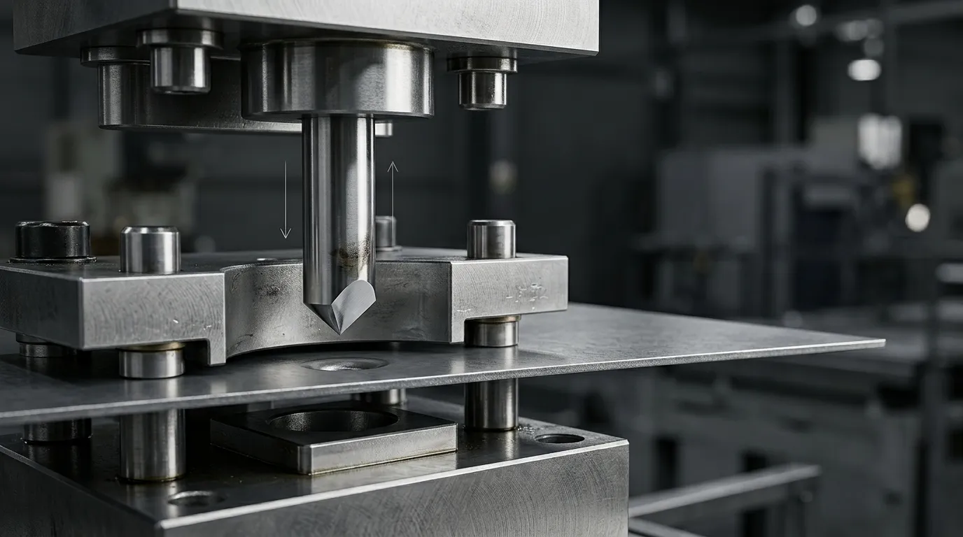
Why High-Tensile Steel Changes Punch-Pin Requirements
Higher-strength sheet places greater demands on the punch, die button, stripper, guide system, and press. The punch must penetrate the sheet without deforming, survive the sudden release of stored energy as the material fractures, and withdraw without excessive adhesion or side loading.
The workpiece description should include more than “high-tensile steel.” Important inputs include:
- Exact steel grade
- Yield and tensile strength
- シート厚
- 表面コーティングまたはメッキ
- Lubrication condition
- Hole size and shape
- Required edge quality
- Production rate and run length
These factors influence cutting load, abrasive wear, friction, galling, burr formation, and stripping force. Two steels with similar tensile-strength ratings can behave differently because their microstructures and surface conditions are not identical.
High-Tensile Steel, AHSS, and UHSS Are Not Interchangeable Specifications
“High-tensile steel” is a broad commercial term. Advanced high-strength steel, or AHSS, includes several material families such as dual-phase, complex-phase, and martensitic steels. UHSS generally refers to the higher-strength portion of this wider group, although terminology can vary by supplier and industry.
The label alone is not enough to select a punch. A tooling supplier needs the complete grade designation, mechanical properties, thickness, and surface condition. Technical overviews of advanced high-strength steel classifications also show why strength numbers should be considered alongside the steel’s metallurgical type.
Higher Loads Can Produce Wear and Fracture at the Same Time
A punch used on higher-strength sheet may experience more than one failure mechanism.
A hard, wear-resistant edge can still chip if it receives uneven loading. A tougher punch may survive impact but lose dimensional accuracy through abrasive wear. Material pickup can increase friction during withdrawal, adding bending stress to a small-diameter punch.
This is why punch life cannot be predicted from hardness alone. Hardness and compressive strength help resist deformation and wear. Toughness and ductility help the tool tolerate impact, bending, stress concentrations, and crack propagation.
Diagnose the Failure Mode Before Changing Punch Material
Before upgrading the punch material, inspect the failed tool and the parts it produced. Look at the cutting edge, flank, body, head, adhered material, scoring direction, burr trend, and the location of any cracks.
The following table provides a practical starting point.
| 観察状態 | 考えられるメカニズム | First checks | Property or correction direction |
|---|---|---|---|
| Gradually rounded edge and increasing burr | 研磨摩耗 | Sheet grade, clearance, surface condition, run length | Greater wear resistance, improved finish, revised clearance or coating |
| Work material attached to the punch | 接着による摩耗や擦り傷 | Lubrication, sheet coating, punch finish, withdrawal condition | Lower friction, better surface finish, suitable coating or process correction |
| Small pieces missing from the cutting edge | エッジチッピング | Alignment, clearance, edge geometry, heat treatment | Greater toughness, lower stress concentration, improved support |
| Major crack or complete fracture | Gross cracking or breakage | Side load, unsupported length, guidance, hardness, punch geometry | Greater fracture resistance plus system correction |
| Edge rolls, mushrooms, or changes shape | 塑性変形 | Cutting load, substrate hardness, heat treatment, compressive strength | Greater compressive strength or corrected heat treatment |
| One side wears or chips faster | Uneven loading | Die-button position, guide wear, press deflection, concentricity | Restore alignment and even clearance before changing material |
その AHSSガイドラインによる金型と金型摩耗に関する議論 separates abrasive wear, adhesive wear, chipping, cracking, and plastic deformation because they do not have the same cause or corrective action.
Abrasive Wear, Adhesive Wear, and Galling
Abrasive wear removes punch material progressively. Common signs include edge rounding, scoring, dimensional loss, and a gradual increase in burr height. Hard phases in the workpiece, scale, surface contamination, and repeated contact can contribute to this type of deterioration.
Adhesive wear involves material transfer between the sheet and punch. The workpiece may stick to the punch surface, creating pickup, smearing, or scoring. Severe adhesion can develop into galling, where rough transferred material increases friction and damages both surfaces.
Before specifying a harder substrate, check:
- Punch surface finish
- Lubricant type and consistency
- Sheet coating
- パンチ・トゥ・ダイクリアランス
- Grinding direction
- Stripping condition
- Existing coating damage
A coating may reduce friction or pickup, but it cannot compensate for severe misalignment, unstable geometry, or an unsuitable base material.
Edge Chipping, Gross Cracking, and Plastic Deformation
Edge chipping is a localized fracture. It may result from inadequate toughness, excessive edge stress, uneven clearance, a sharp stress concentration, poor support, or an unsuitable heat-treatment condition.
Gross cracking affects a larger section of the punch and may lead to complete separation. Side loading, excessive unsupported length, misalignment, poor transitions between sections, or an excessively brittle substrate can contribute. Broader fracture causes are covered in プレス金型のパンチ破損.
Plastic deformation is different. Instead of cracking, the punch permanently changes shape because the applied stress exceeds the material’s compressive capability. The edge may roll or mushroom. A tougher material is not necessarily the answer; the punch may need greater hardness, compressive strength, improved heat treatment, or reduced loading.
Match the Punch Material Family to the Dominant Risk
Material selection should begin with the property that is missing, not with a familiar grade name. The practical question is whether the application primarily needs more wear resistance, toughness, compressive strength, galling resistance, or a balanced combination.
| 物質的家族 | 典型的な選択方向 | 主な利点 | 主な制限 |
| Conventional cold-work tool steel | Moderate to high wear demand with stable loading | Established processing and useful wear resistance | Some grades may chip under severe impact or bending |
| 高速鋼 | Combined hardness, wear resistance, and improved toughness | Balanced performance for many punch applications | Performance still depends heavily on heat treatment and geometry |
| Powder-metallurgy tool steel or PM-HSS | Demanding applications with combined wear and fracture risks | More uniform carbide distribution and broader property combinations | Higher material cost must be justified by the application |
| Carbide | Severe abrasive wear under rigid, well-aligned conditions | High wear and compressive resistance | More sensitive to impact, bending, poor support, and misalignment |
No family is universally superior. A stable, well-supported application with gradual abrasive wear may justify a different material from a small punch that repeatedly chips under side load.
Conventional Tool Steel and High-Speed Steel
Conventional cold-work tool steels can provide strong wear resistance, but their toughness varies widely. A D2- or SKD11-type material may be appropriate in a stable application where abrasive wear dominates, yet it may not be the best direction for a slender punch experiencing impact or uneven loading.
High-speed steels such as M2- or SKH51-type grades are commonly considered when the application needs a stronger balance of hardness, wear resistance, and toughness. This does not make HSS automatically better. Heat treatment, punch diameter, transition radii, guidance, and operating conditions can have more influence than the grade label alone.
SunshinePro lists SKH51, SKH9, and DC53 among its punch-pin material options. These are available choices, not universal recommendations for every AHSS or UHSS operation.
Powder-Metallurgy Tool Steels for Combined Wear and Fracture Demands
Powder-metallurgy production can create a more uniform distribution of alloy carbides than conventional ingot processing. This may allow tool-steel grades to combine high wear resistance with better resistance to chipping or fatigue.
PM materials still have different priorities. Technical guidance may position one grade toward wear resistance and another toward toughness. For example, PM-M4 is often discussed as a wear-focused option, while PM-3V is commonly considered where resistance to chipping and impact carries more weight. These are directional comparisons, not interchangeable specifications.
SunshinePro lists ASP materials among its available punch-pin options. The appropriate ASP grade and heat-treatment condition would still need to be selected from the actual workpiece, geometry, production conditions, and failure history.
When Carbide Helps—and When It Creates New Risks
Carbide offers high abrasive-wear resistance and compressive strength. It can be useful when the die is rigid, the punch is well supported, alignment is controlled, and progressive wear is the main problem.
Its limitations become important in shock-loaded or unstable conditions. Carbide is less tolerant of bending, edge impact, misalignment, and weak support than tougher tool-steel systems. A long, narrow carbide punch can fail quickly if the underlying geometry and guidance are not suitable.
Production volume alone is not enough to justify carbide. The decision should also consider:
- Punch diameter and unsupported length
- Impact and snap-through conditions
- Die rigidity
- Guide-system condition
- エッジジオメトリ
- Regrinding requirements
- Consequences of sudden fracture
Check Clearance, Alignment, and Geometry Before Blaming the Punch Material
A premium punch material will not correct an unstable die system. Clearance, alignment, guidance, rigidity, geometry, and stripping conditions should be checked before a substrate change is approved.
Clearance and Alignment Change the Load on the Cutting Edge
Punch-to-die clearance affects cutting force, fracture development, burr formation, edge loading, and tool wear. The correct value depends on the exact sheet grade, thickness, edge-quality target, tooling condition, and operation. A single clearance percentage should not be applied to all high-tensile steels.
Uneven clearance can be more damaging than an imperfect nominal value. If one side of the punch contacts earlier, that section receives concentrated load and may wear or chip first.
考えられる原因には以下のようなものがあります:
- Worn guide posts or bushings
- Incorrect die-button position
- Punch-holder movement
- Press or die-set deflection
- Assembly error
- Localized die-button wear
その ダイ部品ガイド explains how punches, die buttons, strippers, guide posts, and bushings interact within the wider die system.
Diameter, Unsupported Length, Stripping, and Lubrication Affect Survival
Small-diameter punches are sensitive to bending because their cross-sectional area is limited. Risk increases when the unsupported length is excessive, guidance is weak, or material pickup creates lateral force during withdrawal.
Punch geometry should therefore be reviewed as carefully as the substrate. Important details include:
- Diameter-to-length relationship
- Head and shank design
- 遷移半径
- Cutting-edge preparation
- Relief or taper
- Guidance near the working end
- Stripper support
Stripping can also become a major load event. Material adhered to the punch increases withdrawal force. If the stripper does not support the sheet evenly, the punch may bend as it retracts.
Lubrication and surface finish influence this relationship. They should be evaluated together with the workpiece coating and punch finish rather than treated as general maintenance details.
Treat Heat Treatment, Surface Finish, and Coating as One System
A material grade does not arrive with fixed performance. Heat treatment establishes the final hardness, toughness, compressive strength, stress condition, and dimensional stability. Grinding and surface finishing then influence geometry, friction, and the quality of the cutting edge.
Coating is the final surface intervention, not a replacement for a correctly processed substrate.
Heat Treatment Establishes the Real Punch Properties
The same tool-steel grade can perform differently when its heat-treatment condition changes. Excessive hardness may improve wear resistance while reducing tolerance for impact or stress concentration. Insufficient hardness may allow deformation, edge rolling, or rapid wear.
A responsible specification should define:
- 材料等級
- Required heat-treatment condition
- 許容硬度範囲
- Critical dimensions after heat treatment
- 地表の状態
- 検査方法
- Any post-treatment grinding requirement
SunshinePro lists vacuum heat treatment and precision grinding among its punch-pin processes. The final treatment and inspection requirements should still be agreed for the specific material and drawing.
Coatings Can Reduce Surface Damage but Cannot Repair a Weak Design
PVD coatings can modify friction, adhesive behavior, and wear at the punch surface. They may be useful where galling, pickup, or progressive surface wear dominates.
They cannot correct:
- ミスアライメント
- Excessive unsupported length
- Weak section transitions
- Inadequate substrate toughness
- Plastic deformation beneath the coating
- 誤ったクリアランス
- Poor edge preparation
SunshinePro lists TiN and TiCN as optional punch-pin coatings. Selecting between them requires application-specific review rather than a generic life comparison.
Coating thickness must also be included in dimensional planning. Regrinding may remove the coating from the working area, requiring a decision about recoating, dimensional restoration, or replacement.
Use a Failure-Mode-First Punch Selection Process
A practical selection process should follow this order:
- Identify the workpiece completely.
Record the grade, yield and tensile strength, thickness, surface coating, hardness data where available, and lubrication condition. - Document the punch and die geometry.
Include hole size, punch diameter, head form, overall length, unsupported length, die-button opening, intended clearance, and stripper arrangement. - 失敗を分類しろ。
Determine whether the main problem is abrasive wear, galling, chipping, cracking, deformation, or uneven loading. - Correct system problems first.
Check alignment, guide wear, die-button condition, clearance, press deflection, stripping, and lubrication. - Choose the required property direction.
Decide whether the application needs more wear resistance, toughness, compressive strength, lower friction, or a balanced combination. - Select the substrate and heat-treatment condition together.
Do not choose a grade without defining how it will be processed. - Add finish and coating only where they address the failure mechanism.
Surface treatment should support the substrate and process, not hide an unresolved design problem. - Validate under controlled production conditions.
Monitor burr growth, material pickup, dimensional change, chipping, maintenance intervals, and the condition of the die button.
Consider three common patterns:
- A small punch with repeated edge chipping usually requires alignment and unsupported-length checks before simply increasing hardness.
- A punch with material pickup on coated sheet may need better lubrication, finish, or coating rather than a tougher core material.
- A stable high-volume operation showing gradual edge rounding may justify greater abrasive-wear resistance once clearance and alignment are confirmed.
The best option is the one that controls the actual failure at an acceptable cost per accepted part, not necessarily the punch with the highest initial material cost or hardness.
Prepare the Application Data Before Requesting Custom Punch Pins
A drawing provides dimensions, but it may not explain why the existing punch is failing. A useful technical review should include workpiece data, tooling details, process conditions, failure evidence, and acceptance requirements.
Data to Send with the Drawing or Failed Punch Sample
提供:
Workpiece information
- Exact steel grade
- Yield and tensile strength
- シート厚
- 表面コーティング
- 潤滑剤と塗布方法
Punch and die information
- Punch diameter and profile
- Overall and unsupported length
- Head and shank geometry
- Die-button opening
- Intended clearance
- Stripper and guidance arrangement
- Existing punch material and hardness
- Current coating and surface finish
Production information
- Press type and relevant operating conditions
- Hits per minute
- Hits per run
- Expected production volume
- 再グラインドの歴史
- Planned maintenance interval
Failure evidence
- 鮮明な写真
- Crack or chip location
- Material pickup or scoring
- Burr trend
- Dimensional loss
- Failure frequency
- Whether damage occurs during penetration or withdrawal
SunshinePro states that punch diameter, length, head shape, material, and coating can be customized. Its punch-pin product page also lists SKH51, SKH9, DC53, ASP, carbide, precision grinding, vacuum heat treatment, TiN, and TiCN among available options.
Documentation and Validation to Confirm Before Production
Before approving production, define which records and acceptance criteria are required. These may include:
- Material identity or certificate
- Agreed hardness range
- Critical dimensional inspection
- Surface-finish requirement
- Coating type and thickness
- Dimensions after coating
- Drawing revision
- Sample approval process
- Burr and edge-quality limits
- Regrinding and recoating expectations
SunshinePro’s product page lists dimensional capability up to ±0.002 mm and a hardness range of HRC 58–68. These should be treated as listed capability ranges, not universal specifications. Achievable tolerances and hardness depend on the selected material, geometry, heat treatment, coating, drawing, and inspection agreement.
For an application review, send the drawing together with the sheet specification, operating conditions, and failure evidence through the SunshineProの連絡先ページ. This gives the supplier enough context to evaluate the punch material, geometry, heat treatment, finish, and coating as one system rather than recommending a grade from the workpiece name alone.
シェア:


脚本:トンモイ
ニュース
サービスを受けましょう
あらゆる予算に合った高品質な部品と、親切なスタッフが訓練されており、訪問を有益で手間なく提供します。
